
Related Manuals for Succeeder SF-8100

Summary of Contents for Succeeder SF-8100
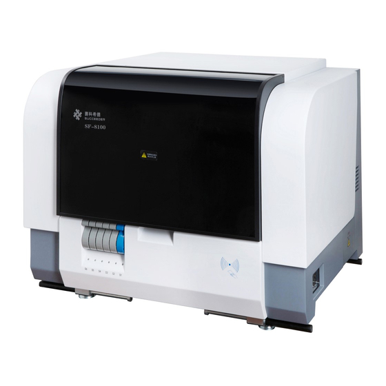
- Page 1 SF-8100 Automated Coagulation Analyzer Beijing SUCCEEDER Technology Development Co., Ltd.
-
Page 2: Table Of Contents
1. Table of Contents 1. Table of Contents ..........................2 2. Warnings and Cautions ........................5 2.1. General Warnings ........................... 5 2.2. Safety of Login ..........................5 2.3. Warning before use ........................5 2.4. Quality Commitment ........................6 3. Circuit diagram and description ..................... 7 3.1. - Page 3 7.4. Daily maintenance ........................38 8. Storage ............................39 9. Troubleshooting ..........................40 10. Symbols ............................44 11. Circuit description & map ......................45 12. Special tools ............................ 46 13. Spare part list ..........................47 14. Index ..............................48...
- Page 4 Read this manual carefully before use. Model: SF-8100 Name: Automated Coagulation Analyzer Manufacturer: Beijing Succeeder Technology Development Co., Ltd Service hotline: Please contact with local authorized representative. Fax: +86 -10-89701711 Address:Tower 1A, No. 27 Chuangxin Road, Changping District, Beijing 102200, China Postcode: 102200 http://www.succeeder.com.cn...
-
Page 5: Warnings And Cautions
SF-8100 analyzer system. Succeeder shall not be held responsible if the procedures described in this manual are not strictly observed, or if procedures not described in this document are used. Read the SF-8100 Operator’s Manual carefully and respects all the instructions given therein. -
Page 6: Quality Commitment
temperature humidity For unpacked machine: Indoor -20℃~55℃, relative below 93%, no corrosive gas and drafty indoor. Not apply in damp environment. Power supply must be grounded firmly. A leakage protector is needed in damp environment. power stabilizer. UPS Our product was designed with was recommended when the power supply in user field was not stable that the voltage of wave... -
Page 7: Circuit Diagram And Description
3. Circuit diagram and description The instrument is designed in a modular format consisting of a power module, movement module and a sensor module. The electrical module contains the power supply and other boards which contains all components, 3.1. Power module The power module can be described in three sections: the power supply, the voltage regulator, and the power board. -
Page 8: Movement Module
3.2. Movement module The movement module is a unit that contains mechanism of manipulator, arm with XYZ direction, probes and other necessary parts. Communication system Sample Temperature and cuvette Test Clean status loading release Temp control XYZ move Magnetic bead pipeline Inflow/outflow detach... -
Page 10: Technical Specification
Test principle: Test method: Clotting method, optical method ( chromogenic substrate method and immunoturbidimetric method). Judgment method: Eddy current sensor, optical colorimetric, turbidimetric. SF-8100: Clotting method、optical method. Test sample: Platelet-poor plasma using sodium citrate as anticoagulant (PPP). Accuracy and reproducibility Item... -
Page 11: Description Of Device
Intended Use For in vitro Diagnostic Use Only. SF-8100 is an automated laboratory instrument designed to perform in vitro tests which aid in the diagnosis of coagulation abnormalities as well as to assist in monitoring anticoagulant therapy. The instrument is capable of performing clotting assays on plasma samples. -
Page 12: Chromogenic Substrate Method
Clotting Ball Motion Schema 5.4. Chromogenic substrate method Enzymes are proteins that catalyze most of the chemical reactions that take place in the body. They make it possible for chemical reactions to occur at neutral pH and body temperature. The chemical compound upon which the enzyme exerts its catalytic activity is called a substrate. -
Page 13: Procedure Description
5.6. Procedure Description The plasma is pipetted by sampling probe then distributed in a cuvette of incubation site. If the first reagent is needed, the sampling probe will pipette the first reagent to the cuvette of incubation site. When reaching incubation time, cuvette-hooking system startup, hooking the cuvette of incubation site to test site. -
Page 14: Installation Instruction
Installation instruction 6.1. Appearance; 6.1.1. External structure. 3. Upper cover 1. Left cover 4. Swiping area 2. Switch & ports 5. Sample racks 6. Right cover 7. Waste box 8. Connectors 9. Rinse button External structure; 1. Left cover 2. Switch & ports 3. - Page 15 Power switch Power connector USB port Network port Sensor connector of Sensor connector of waste liquid box cleaning water box Tube connector of Tube connector of waste liquid cleaning water Working space 6.1.3. Working Space; 1. Manipulator 2. Sample incubation area 4.
-
Page 16: Parts Description
Cuvette outfall 7. Cleaning position 8. SFT position x2 9. Reagent area 10. Sample area 1. Manipulator. 2. Sample incubation area. 3. Test area. 4. Sample probe. 5. Reagent probe. 6. Cuvette outfall. 7. Cleaning position. 8. SFT position x2. 9. - Page 17 positions. Incubation positions. c. Test area. It is designed for testing with methods of magnetic and optics. It contained with 4 positions that can be test separately. 4 test positions. d. Sample probe &Reagent probe. Two probes are designed for suck sample and reagent. The left one is sample probe, the right one is reagent probe.
- Page 18 Cuvette outfall Cleaning position. It is designed for clean both probes with cleaning liquid. Cleaning position g. SFT position x2. The two SFT positions are designed for clean probes with special cleaning fluid. SFT position x2 h. Reagent area. The area is designed for placing reagent. It consists of 36 positions that separated by room temperature area and cooling area, left part for keep reagent in room.
-
Page 19: Cuvette Supply System
Sample area. It consists of six racks which contained 60 sample positions. Sample area 6.3. Cuvette supply system; Cuvette supply system 6.3.1. Structure of Cuvette supply system; 2. Cuvette roll 1. Roll Locker... -
Page 20: Carry-Handles
3. Cuvettes 4. Upper roller Lower roller 5. Lower roller 7. Tighten roller 6. Locker 1. Roll locker 2. Cuvette roll 3. Cuvettes 4. Upper roller 5. Lower roller 6. Locker 7. Tighten roller 6.4. Carry-Handles; Four carry-handles are located at four lower corners that designed for carry machine easily. Carry-handles 6.5. -
Page 21: Unpack Machine
6.6. Unpack machine Step1. Cut off Straps Step2. Take the box cover off... - Page 22 Step3. Take out attachments as circled in photo.
-
Page 23: Parts Release
Step4. Put Machine on the table by holding the 4 Carry-handles in each corner (2 persons at least for carry.) Carry-handle 6.7. Parts Release. Step1. Untie the belts. Step2.disassemble the fixing foams. - Page 24 Step3. Unscrew the bolt which fixed on the two of shaft. Step4. Take off the foam which fixed the manipulator unit.
-
Page 25: Connection
6.8. Connection Inflow connector Outflow connector Step1. Screw the outflow unit to waste liquid barrel, and connect the other ends to connector of machine as following photo. Outflow unit DC connector Outflow Tube Step2. Screw the inflow unit to cleaning water barrel, and connect the other ends to connector of machine as following photo. -
Page 26: Cuvette Rolls Installation
DC connector Inflow unit Inflow tube Step3 put the barrels to a position that closed to machine as below; 6.9. Cuvette rolls Installation. Step1. Open the cover of cuvette supply system that using pull-handle at left side of machine follows the guide trace (up for open, down for close) Step2. - Page 27 Step3. Put the cuvette line through two rolls. Step4. Open the part circled in photo, put the end of cuvette through and lock it. Step5. Put the end of cuvette in position and lock it.
-
Page 28: Connect To Computer
6.10. Connect to computer. One computer is necessary for run the SF-8100, printer is recommended unit as option. Connect Network Cable, USB cable, and power cord to Machine located left hand side. Power cord Network USB cable cable Step4. Connect the other ends to computer... -
Page 29: Software Installation
6.11.1. Put the installation CD to ROM driver. 6.11.2. Install VSPM. Step1. Open the compressed file “ ” in path D:\SF-8100 installation\VSPM Install vspm as default settings until complete. Step2. Once the “VSPM” installed successful the VSPM screen will appear as follow;... - Page 30 (Step2.) If it isn’t appeared automatically, start it manually by click from C:\Program files\VSPM. Or from start menu as photo below; Step3. Go to Config page. Step4. Remove the tick at the “Enabled keep alive” as in figure; Remove the tick Step5.
- Page 31 5-10. Set COM7 (For example). Tap “192.168.1.8” in the Server IP field, Tap “1024” in the Server Port. Click OK. Step10. Double click the file “vspmctl” (C:\Program Files\VSPM) to install VSPM Service. 6.11.3. Install SF-8100 V1.1, Double click the file “Setup.exe” in software DISC; install it with all default settings until...
- Page 32 Step1. Go to Control panel, find the “Local Area connection properties”, and enter “Internet Protocol (TCP/IP)” Step2. Set Indicated IP address as 192.168.1.230 Step1. Activate Step2. Input IP address option. and subnet mask. Step3. Set “Subnet mask” as 255.255.255.0 Step 4. Save settings by click “Ok” Step5. Restart computer, and startup SF-8100.
-
Page 33: Software Introduction
Virtual serial will lead problem to the software of SF-8100. 6.12.2. Startup Program. Double click the Icon” SF-8100” on the desktop to startup the program. Quick launch icon 6.12.3. Initializing screen. -
Page 34: Routine Test
Login window 6.13. Routine test Theme Steps Description Startup Procedure Power on machine, printer, PC, start-up SF-8100 program. Take blood Refer to procedure Sodium citrate(Anticoagulant 109mmol/L), 1: 9 (Anticoagulant: blood) Anticoagulation Sample preparing Centrifuging Centrifuge blood with speed 3000rmp/Min, time:10-15Min... - Page 35 Loading sample Bulk/single/STAT Refer to test procedure Input Input information Operate in program Query Operate in program Query&Print Select report; click “Print” to print out the report. Report printing Clean the probes and platform, and click “Maintenance” in toolbar. Maintenance Probes Click “Rinse “to fill-in the washing solution.
-
Page 36: Maintenance
The instrument should be placed on a firm workbench without any shake or shock. Avoid exposure to straight sunshine, and keep away from source of strong heat. 7.3. Communication analyzer 7.3.1. Com port analyzer. C:\Program files\Succeeder\com expert Attention: close program SF-8100 before run COM EXPERT. COM Port Number Feedback area Input area Command... - Page 37 Communication failure occurs if no feedback with command which last letter is “A”. COM5 A012.0.001347F5 Main board B011.0000F428 Magnetic bead method board COM6 C011.0.009BD48 Optics method C00A01 Optical filter motor D011.0.0002259E Rack board Status check(cover open/close) COM7 Magnetic switch command E012.0.001136F0 Heating &...
-
Page 38: Daily Maintenance
7.4. Daily maintenance FREQ Time Method Purpose Maintain pipeline, remove bubble, to avoid wrong sample amount. click “ rinse" After Turned on Ensure consumable items Ensure SFW/SFT enough to avoid enough. wrong sample amount Every day Maintain pipeline, remove bubble, to avoid wrong sample amount. -
Page 39: Storage
Storage Preservation condition for sound package – indoor, and -40~55 ℃, relative humidity must be lower than 93%, no corrosive gas, proper ventilation; temperature difference >10℃, keep analyzer under room Do not use immediately if temperature for 24 hours before turning on; ... -
Page 40: Troubleshooting
Troubleshooting Problems Solution Cuvette system Hook cannot reach cuvette position 1. Use sharp tool to touch microsensor, make it reset correctly. 2. Check whether it is specified cuvette. 3. Reload cuvette. Cuvette cannot be catched up. 1. Clear incubation channel and test channel to remove foreign matter. - Page 41 direction. Change a new motor board for hook horizontal movement, and REMEMBER to change its code, and this board code is 0110. You may follow the old/original board to change the code. Check the cable if it is broken or disconnected, or insert with wrong direction.
- Page 42 5. Check if optical fiber broken or not. 6. Replace lamp if solution above not work If individual light shade not in the rage. 1. Clean optical fiber ends inside test channel. Red-light:2.0-4.5; 2. Remove fiber from test channel; clean both ends with Purple-light: 1.0-4.5 lens paper.
- Page 43 Connect motion control system error 1. Start VSPM, setup correctly. 2. Check whether Comport is being used. 4. Check RJ45 network cable, 5. RJ45 communication error(ping 192.168.1.8 to check) 6. Check connection of communication board 7. Replace main control board Use “...
-
Page 44: Symbols
10. Symbols Cleaning solution Attention Waste solution Potentially Fuse protector biohazardous liquid Protective earth Communication Port (ground) Danger... -
Page 45: Circuit Description & Map
11. Circuit description & map The layout of the SF8100 is illustrated in the circuit diagram as following:... -
Page 46: Special Tools
12. Special tools ˆ Tools requirement Digital multimeter (DMM) Computer or remote data terminal and connection cable for RS232 communication Wire strippers Soldering iron Orifice removal tool Assortment of 1/4” and 1/8” tubing and fittings pliers ... -
Page 47: Spare Part List
13. Spare part list Part name Part number Optical cable kit SF-810-P0001 Master control board SF-810-P0002 Optical control A-board SF-810-P0003 Optical control B-board SF-810-P0004 Magnetic control A-board SF-810-P0005 Magnetic control B-board SF-810-P0006 Sample probe control board(Level sensor board) SF-810-P0007 Sample probe temp board SF-810-P0008 LED indicator board SF-810-P0009... -
Page 48: Index
14. Index Accuracy ..............................10 Appearance; ............................14 Application ............................. 11 Carry-Handles ............................20 Chromogenic ............................12 Circuit ............................... 7, 45 Cleaning ..............................18 Communication .......................... 33, 37, 45 Connection............................25, 29 Cuvette ..........................17, 20, 27, 41 Description ............................. 11 Danger ..............................
Need help?
Do you have a question about the SF-8100 and is the answer not in the manual?
Questions and answers