Table of Contents
Advertisement
Quick Links
Advertisement
Table of Contents

Related Manuals for DTG-C Model X


Summary of Contents for DTG-C Model X
- Page 2 Important Notice For Users in Europe MPORTANT This is a Class A product approved for industrial environments. In some environments this product may cause radio interference in which case you may be required to take measures to re‐locate this product. For Users in the United States This equipment has been tested and found to comply with the limits for a Class A digital device, pursuant to Part 15 of the FCC Rules. These limits are designed to provide reasonable protection against harmful interference when the equipment is operated in a commercial environment. This equipment generates, uses, and can radiate radio frequency energy and, if not installed and used in accordance with the instruction manual, may cause harmful interference to radio communications. Operation of this equipment in a residential area is likely to cause harmful interference in which case the user will be required to correct the interference at his own expense. Trademarks Mentioned in this Manual: DTG‐C and Model X are registered trademarks or product names of DTG CONNECTION Pty Ltd. EPSON® and EPSON STYLUS® are registered trademarks of Seiko Epson Corporation. Microsoft®, Windows®, and Windows Vista® are registered trademarks of Microsoft Corporation. Apple® and Macintosh® are registered trademarks of Apple Inc. Intel® is a registered trademark of Intel Corporation. PowerPC® is a registered trademark of International Business Machines Corporation. Adobe®, Photoshop®, Elements®, Lightroom® and Adobe® RGB are registered trademarks of Adobe Systems Incorporated. G e n e r a l N o t i c e : O t h e r p r o d u c t n a m e s u s e d h e r e i n a r e f o r i d e n t i f i c a t i o n p u r p o s e s o n l y a n d m a y b e t r a d e m a r k s o f t h e i r r e s p e c t i v e o w n e r s .
- Page 3 DTG CONNECTION warrants part repair or replacement as a sole measure only if a failure is found in the system or in the materials and workmanship of the product the seller produced. However, if the cause of failure is uncertain or cannot be conclusively proved to be directly related to defect in workmanship any part repair or replacement shall be solely at the discretion of DTG CONNECTION. The warranty shall not apply to any direct or indirect loss, or compensation for the loss due to the product that has been subject to misuse, neglect, or improper alternation whether directly or indirectly. ALL INFORMATION CONTAINED IN THIS DOCUMENT IS PROVIDED AS IS WITHOUT WARRANTY OF ANY KIND. THE CREATOR OF THIS DOCUMENT, HEREINAFTER REFERRED TO AS THE 'WRITER' HEREBY DISCLAIMS ALL WARRANTIES, EXPRESSED, IMPLIED OR OTHERWISE, INCLUDING WARRANTIES OF MERCHANTABILITY, FITNESS FOR A PARTICULAR PURPOSE, AND NON‐INFRINGEMENT OF INTELLECTUAL PROPERTY RIGHTS. THE WRITER DOES NOT ASSUME OR AUTHORIZE ANY OTHER PERSON TO ASSUME FOR IT ANY OTHER LIABILITY IN CONNECTION WITH THIS SITE CONTENT. IN NO EVENT SHALL THE WRITER BE LIABLE TO THE READER OF THE CONTENT OF THIS SITE, OR ANY SUBSEQUENT USER, INCLUDING THE ULTIMATE END‐USER, IN CONTRACT, TORT, WARRANTY, STRICT LIABILITY, OR OTHERWISE FOR ANY SPECIAL, INDIRECT, INCIDENTAL OR CONSEQUENTIAL DAMAGES, INCLUDING BUT NOT LIMITED TO, THE COST OF LABOR, REQUALIFICATION, DELAY, LOSS OF PROFITS OR GOODWILL, EVEN IF THE WRITER IS ADVISED OF THE POSSIBILITY OF SUCH DAMAGES. BY LOOKING AT THE CONTENT OF THIS DOCUMENT THE READER AGREES THAT THEY HAVE READ AND AGREE TO THE ABOVE CONDITIONS ENTIRELY.
-
Page 4: Table Of Contents
Contents INTRODUCTION General Specifications ............................. 4 Overview Of User Interface ............................. 5 1.2.1 Home Screen ............................. 5 1.2.2 Status Screen ............................. 5 1.2.3 Printing Screen ............................ 6 1.2.4 Maintenance Screen .......................... 6 1.2.5 Adjustment Screen ............................ 7 1.2.6 Replacement Screen .......................... 7 1.2.7 Setting Screen ............................ 8 INSTALLATION Installation ................................ 9 Printing .................................. 11 2.2.1 Setting Platen ............................ 13 2.2.2 Pause & Cancel The Printing ........................ 14 2.2.3 Data Path Flowchart .......................... 16 USER INTERFACE Home Screen ................................. 17 ... -
Page 5: Contents
Contents 4.1.6 Dc Motor Carriage Module ........................ 44 4.1.7 Main Controller Board Module ....................... 45 4.1.8 Actuator Unit Valve Module ........................ 48 Replacing Maintenance Unit .......................... 49 Replacing Spitting Box ............................ 51 4.3.1 Left Ink Sump Replacement ........................ 51 4.3.2 Right Ink Sump Replacement ........................ 52 Replacing Ink Supply Module .......................... 53 4.4.1 Ink Supply Unit ............................ 53 SETTING SCREEN Ink Path Control .............................. 54 5.1.1 Charging White Channel with Cleaner ..................... 55 5.1.2 Charging All Channels with Ink ........................ 55 5.1.3 Charging With White Ink ......................... 55 Option .................................. 56 5.2.1 Ip Address ... - Page 6 Contents... continued 6.4.14 Set Head Rank [DBG] ........................70 6.4.15 Time Set [SVC/MFG] ........................71 6.4.16 Ip Initialize [SVC] .......................... 71 6.4.17 White Timer Reset Config [DBG] ....................71 6.4.18 Ink End Threshold & Purge Interval [DBG] ..................72 6.4.19 Set Ink Type [SVC/MFG] ........................ 72 6.4.20 Set Temperature Offset [DBG] ...................... 72 6.4.21 Reset Initial Charging Flag [SVC] ....................73 6.4.22 Drop Count Management [DBG] ....................73 6.4.23 Table Adjust [SVC/MFG] ........................
-
Page 7: Introduction
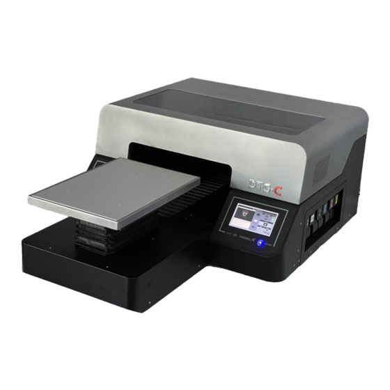
1. INTRODUCTION This guide explains the basic functions, specifications, theory of electrical, mechanical operations and replace procedures of the DTG‐C MODEL X printer. This guide included herein are intended for the experienced replacement technicians and attention should be given to the precautions. And also this document is written with android panel v.1.31.4. 1.1. General Specifications CONTENTS SPECIFICATIONS 34” x 52” x 18” / about 216lbs– Size (with housing) / Weight Large 406 x 508mm (16″ x 20″) Maximum Print Size (Bed Size) Medium 320 x 457mm (12.6″ x 18″) Small 266 x 330mm (10.5″ x 13″) Table Height Adjustment Automatic / 1.25” (depends on bed height) Ink Type Pigment garment ink ... - Page 8 1.2. Model X Printer Overview 1.2.1. Printer’s Front Front Cover Open the front cover for maintenance. Otherwise keep it closed. Ink Cartridges Access ...
- Page 9 1.2.3. Under the Cover Flushing/spitting Box It collects the ink discharged during the flushing operation. A message will be displayed when it needs to be replaced Carriage Underneath there is the print head and the head nozzle. It moves left and right when printing. The carriage requires regular cleaning Head Cap It prevents the print head from drying out Wiper It is a gum plate that wipes the ink off on the print head ...
- Page 10 1.3. Regarding Use Do not turn the power off. • This printer periodically circulates ink internally and automatically performs head cleaning. If you do not use the printer for more than 7 days, it is recommended to flush white ink out with cleaning carts. • Perform maintenance at least once per week. This printer performs automatic maintenance periodically. But it requires manual maintenance weekly, the ink in the cartridge could settle and/or coagulate, causing poor image quality or printer failure. If weekly maintenance is neglected, carriage warranty will be voided Some parts require periodical replacement. • This printer includes parts that require replacement due to usage. Keeping the printer maintained will help to avoid getting “Errors”. • If this printer gets an error, maintenance function may not be working. Then watch the printer status periodically and report to technical support right away. 1.4. Power Power Connector AC Power Switch Power On/Off ...
-
Page 11: Overview Of User Interface
1.5. Overview of User Interface 1.5.1. Home Screen Item # Item name Description Print home screen with print preview Set position of platen, print, eject, pause and stop Adjust platen height by pressing or holding this button Select platen height adjustment method, auto or manual Select from recent print jobs Select to access the maintenance menu Select to access the USB to find print jobs on USB drive Select to access the printer settings menu Printer status display, ready, notifications and errors, etc. Display shows temp and humidity, if pressed takes you to ink and waste levels screen ... - Page 12 1.5.2 Recent Jobs The user can check the print information of recently printed jobs and select the reprint function. It also can remove recently printed information. The user can view and print a list of print image data stored in a USB. Item # Item name Description View recently printed job from image Select highlighted job for reprinting Save the highlighted job, don't allow deletion Save highlighted job to inserted USB Delete highlighted job Return to the home screen ...
- Page 13 1.5.3 USB You can access the USB by selecting the [USB] button on [Stored job] dialogue box. Item # Item name Description Check and select print files on the USB drive Select highlighted job for reprinting Save the highlighted job, don't allow deletion Save highlighted job to inserted USB Delete highlighted job Return to the home screen ...
-
Page 14: Maintenance Screen
1.5.4 Maintenance Screen Item # Item name Description Print a nozzle check pattern (Must set table first) Access parts replacement screen Access automatic print head cleaning screen Release carriage to perform manual maintenance Adjust platen height Set platen in or out (must be in to perform a nozzle check) Activate automatic platen height adjustment Return to home screen ... - Page 15 1.5.5. Settings Screen Item # Item name Description Access alignment menu to align table, heads, etc Access IP address and network settings menu Access temp menu to change between C and F Activate or deactivate obstruction sensor (turning off may result in carriage damage) Reset printer to factory settings Access sounds menu Access printer system info screen Return to home screen...
- Page 16 1.5.6 Alignment Screen Item # Item name Description Print head adjustment pattern Print platen adjustment pattern Print adjustment pattern for print position Access new table alignment menu Set or eject platen Manually adjust platen height Activate or deactivate auto platen height Return to home screen 1.2.1 Replacement Screen ...
- Page 17 Display the usage, date of replacement for the replacement parts. And perform replacing process for each part. Left spitting box/sump Print head carriage Right spitting box/sump Maintenance station/capping station ...
- Page 18 White ink bay Cyan and Black ink bay Magenta and Yellow ink bay Return to home screen ...
-
Page 19: Installation
2. INSTALLATION 2.1 Installation Open the front cover and Connect waste ink bottle tube to valve on remove bracket fix platen. the right‐back side of printer. WARNING - The printer will not know if waste ink bottle is connected, be sure the waste ink bottle is connected. ... - Page 20 Hold down the sub power button for more than 3 seconds. STAR T • To turn the power on ‐ hold down the sub power for more than 3 seconds. • To turn the power off ‐ hold down the sub power for more than 5 seconds. CAUTION - Make sure that the main power switch and sub power are always turned on. If you do not, the ink in head could settle and/or coagulate, causing poor image quality or printer failure.
- Page 21 Finishing initial charging, the printer shows “Ready” REFERENCE - This printer uses ethernet to send the printing data. If ethernet is not set up, you will need to use an external USB drive to print. WARNING If ’t 2.2 Setting platen ...
- Page 22 2.2.1 Up & Down The printer’s platen height can be adjusted manually using the up and down arrows: • Short Touch ‐> moving slightly up or down. • Long Touch ‐> moving continuously up or down. 2.2.2 Auto & Manual platen adjustment Auto Manual You can choose automatic or manual height adjustment. • On the automatic mode the height of platen is adjusted automatically when the platen is moving. The maximum height of the platen is reached on the initial movement of the platen. • On the manual mode the movement of the platen is stopped by a sensor. ...
- Page 23 2.2.3 Moving the Platen This is used for moving the platen to print position. • Platen starts out, for loading garment. • In the automatic mode, height of platen is adjusted automatically • If the platen is stopped when moving to print position you have to select [Eject] to return to the position for placing T-shirt on platen. Stop •...
-
Page 24: Printing
2.2.4 Obstacle Detection If obstacle sensor detects something when repositioning platen in manual mode this dialogue box is displayed. Lower the height of platen. 2.2.5 Cancel, Pause and Resume printing Press the [CANCEL] to cancel the printing On the printing, press to [stop], printer is paused and pop‐up dialogue box as below. Press the [RESUME] button to re‐start the printing. • . ... -
Page 25: Data Path Flowchart
2.3 Data Path Flowchart If you have installed RIP software and MODEL X DTG‐C has no error, you are ready to print. But, remember the requirements below: At anytime the MODEL X DTG‐C can receive (or pend) the print data. But, to start printing, platen should be set to print start position. To set the platen press button “LOAD” on the panel. If print data is pending into printer has no error and platen is set ‐ printing process is started. ... -
Page 26: Home Screen
3. USER INTERFACE Home Screen 3.1.1 Setting Platen Please refer 2.2.3 Setting Platen ... -
Page 27: Maintenance Screen
3.2 Maintenance Screen You should perform regular maintenance to maintain the printer’s performance. The user can access these functions through this tab. Built‐in scheduled maintenance is listed below. White ink circulation Every hour White channel cleaning Every 3 hours All ink cleaning ‐ alarm for agitating white cartridge Every 12 hours Alarm for manual cleaning Every 7days WARNING - If the printer is off or has an error status, the maintenance function will not operate. Always keep the printer ready. -
Page 28: Nozzle Check
3.2.1 Nozzle check • You can check the nozzle condition with this button. • Make sure to check the nozzle condition before printing T‐shirt. • If there is nozzle clogging, perform head cleaning until the problem is resolved. Prepare the A4 transparent media to check nozzle condition (to check white nozzle, transparent media is required). Prepare medium‐size platen. Nozzle check pattern is based on medium platen, aligned on top‐center. (Additionally, all built‐in patterns are based on this platen). Attach media on the platen aligned top center using masking tape or sticky spray. Move the platen to the printing position, press [Nozzle Check] button. And check the results of printed nozzle check pattern. ... -
Page 29: Automatic Head Cleaning
3.2.2 Automatic Head Cleaning When there is nozzle clogging or faded lines the print head will need to be cleaned. This printer has an automatic head cleaning function. You can press this button to perform automatic print head cleaning. In this box, user can choose the channel to clean, with the option of normal and strong. Off If after normal cleaning is complete and nozzle condition is not improved, then perform strong cleaning. WARNING - Strong cleaning consumes more ink. (Normal cleaning 0.49cc, Strong Cleaning 3.09cc) ... -
Page 30: Manual Head Cleaning
3.2.3 Manual Head Cleaning If nozzle status has not recovered with automatic head cleaning, then you have to clean the head manually. ** Weekly, regular manual cleaning is mandatory! Selecting this moves the print head to the center of bridge. Then you can clean the face of nozzle manually. Onc Once the carriage has moved to the center, power down the machine at the switch in the back. Use a damp lint free wipe or swab to gently rub off dried ink around the heads. -
Page 31: Agitating White Cartridge Alarm
3.2.4 Agitating White Cartridge Alarm When using white ink, shake the ink cartridge every 12 hours to avoid ink sedimentation and coagulation. When this alarm dialogue is displayed you have to shake the white cartridges smoothly to prevent damaging the ink bag inside of cartridge. This dialog will be closed by opening cartridge cover. WARNING - DO NOT shake cartridge too fast or hard too avoid tearing the ink bag inside cartridge. 3.2.5 Manual Cleaning Alarm ... -
Page 32: Empty The Waste Ink Bottle
3.2.7 Empty the Waste Ink Bottle When the waste ink bottle is full the following message is displayed on the touch panel. You can check the amount of waste ink on the [Status Panel] and reset the waste ink counter. To reset the waste ink counter after emptying the waste ink bottle, select [WASTE I NK R ESET]. WARNING - Ensure you have to emptied the waste ink bottle before resetting the waste ink counter. -
Page 33: Adjustment Screen
Adjustment Screen This section describes how to adjust this printer for good image quality with the touch panel. Although the printer head nozzle status is good, the print quality may not be good. You will need to perform this adjustment process. These functions can be performed through the [Maintenance] screen. 1. Prepare the A4 transparent media and medium‐size platen. 2. Attach media on the platen aligned Top‐ Center using masking tape or sticky spray. 3. Move the platen to the printing position then press each adjustment button. -
Page 34: Adjusting Head
3.3.1 Adjusting Head This function adjusts the print head position. When the print result is not clear (for example, vertical lines are misaligned, or colour is not clear.) this adjustment may improve the result. Select this button, the pattern of adjusting head is printed. After pattern is printed find an appropriate adjustment value from the print result to adjust pattern. Find a pattern with a square in the lightest colour and with vertical lines on both sides aligned. A value indicated over the pattern indicates an appropriate ... -
Page 35: Adjusting Platen
3.3.2 Adjusting Platen The printing position can be adjusted. If the print result has a line of horizon, you need to do this function. Select this button for print position. Find an appropriate adjustment value from the print result of adjustment patterns. ... - Page 36 Find a pattern with a square in the lightest color and horizontal lines on both sides aligned. A value on the upper of the pattern indicates an appropriate adjustment value. An appropriate adjustment value is “+6”. In some cases, an adjustment value is an in‐ between value of patterns When a square is in the lightest colour but horizontal lines on both sides are misaligned. In the this illustration a square in the lightest colour is “+6”, but horizontal lines on both sides are misaligned. In this case check horizontal lines for one pattern above and one pattern below of the square. ...
-
Page 37: Adjusting The Printing Position
3.3.3 Adjusting the Printing Position The printing position can be finely adjusted within the range of ±4mm. The upper button is for adjusting the printing position. After printing the pattern of adjusting printing position you have to find appropriate value. ... -
Page 38: Replacing Consumable Parts
4. REPLACING CONSUMABLE PARTS This printer has some replaceable consumable parts. You can check the status these parts with [Replace] screen shown as below. Each button indicates the parts requiring replacement. Select the button, the part replacement ... - Page 39 ...
-
Page 40: Encoder Strip 17Inch
Carriage 4.1 Replacing Related Parts 4.1.1 Encoder Strip 17 Inch Turn off the printer power. Unlock the carriage and push it completely to the left side or center of the printer as below. Rotate the black lever counter‐clockwise until the arrow on the lever aligns with the arrow marked “C” below. When the triangles are aligned, the carriage is unlocked. Move printhead to the middle. Release encoder strip on maintenance unit side. The encoder strip is elastic so it can be pulled. Pull and remove strip. ... - Page 41 Remove encoder strip on print head. Release encoder strip on left spitting box side. Hang encoder strip on the left spitting box side. Insert encoder strip into print‐head. ...
- Page 42 Hang Encoder Strip on the maintenance unit side. Move print head to maintenance unit side. Turn on the printer power. ...
-
Page 43: Carriage Unit
4.1.2 Carriage Unit Before replacing print head, it is necessary to flush the ink out of the print heads. Select the maintenance menu and then Ink Path Control and flush ink from system ... - Page 44 Select the manual maintenance button and once the carriage moves to the center of the rail, flip the power switch to the off position. If the carriage needs to be released manually, shut down printer at power switch and release carriage from maintenance station by rotating the white lever counterclockwise to align triangles. Then slide carriage to middle of rails. 1. Open the printer top cover case. 2. Unlock the carriage 3. Push the carriage to the center. Press on the carriage itself as shown, not the top cover.
- Page 45 .1.1.2 4. Remove the Encoder strip 17 inch. 5. Disconnect the vertical arm of the spring and remove (Reference 4.1.1). it. 6. Remove the guide lock linkage. 7. Push the carriage all the way to the left side of the machine until it stops. 8. Attach the jigs. Remove screw and cam. ...
- Page 46 Attach the holder to the end of the rod Disconnect the bottom half of the carriage and pull the rod out as far as the first timing belt from the back of the carriage. jig. Remove the carriage and HRB cover. When complete this dialogue box will appear to reset the amount of head usage and replacement date. Remove the FFC harness and ink tube. (Reference 4.1.3). Replace the carriage. Assemble in reverse order of disassembly. ...
-
Page 47: Ink Tube
4.1.3 Ink Tube Turn off the printer power. Open the printer top cover. Remove the cover of carriage and MODEL X DTG‐C junction board. Remove the Ink tube attached to the old carriage and insert the cap to end of ink tube. ... - Page 48 Separate the tube from the plate tube rhe ‐ loosen one bolt. Remove the ink tube fix bracket ‐ loosen the four b olts. Remove the Ink tube on the ink supply unit (Reference 4.4.1). ...
- Page 49 Assemble the ink tube to the plate tube and ink tube fix bracket. Align the guide line to the middle of the plate tube hole. Assemble the ink tube to the carriage. ...
- Page 50 Assemble the new ink tube to the ink supply unit. Turn on the printer power. ...
-
Page 51: Timing Belt - X Axis
4.1.4 Timing Belt – X Axis Turn off the printer power. Remove the encoder strip (Reference 4.1.1). Remove the carriage unit (reference 4.1.2). Remove the spring pressure roller ‐ remove using long nose pliers. Push the pressure roller inward and remove the timing belt. Assemble a new timing belt. Assemble the carriage unit and encoder strip. Turn on the printer power. ... -
Page 52: Pressure Roller Assembly
4.1.5 Pressure Roller Assembly Turn off the printer power. Remove the carriage unit (reference 4.1.2). Using long nose pliers remove the spring pressure roller and remove the timing belt (reference 4.1.5). Push the pressure roller inward to remove it. Pull to the marked hole and remove. Assemble the new pressure roller by pushing it outward. Insert into the marked hole and push to assemble. Assemble the timing belt, the carriage unit and encoder strip. Turn on the printer power ... -
Page 53: Dc Motor Carriage Module
4.1.6 DC Motor Carriage Module Turn off the printer power. Remove the encoder strip. (Reference 4.1.1) Remove the carriage unit. (Reference 4.1.2) Remove the timing belt x‐axis. (Reference 4.1.5) Remove the harness connected to the DC motor. Loosen the two bolts. Assemble the new DC motor. Assemble the timing belt, carriage unit and encoder strip. Turn on the printer power. ... -
Page 54: Main Controller Board Module
4.1.7 Main Controller Board Module Main Controller Board Unit 4.1.7.1 Turn off the printer power. Remove the printer top cover case. Remove the CTL cover. Loosen the four bolts. Remove the harness connected to the CTL board. Loosen the six bolts. ... - Page 55 Assemble the new CTL board and connect harness. Assemble the CTL cover and printer top cover. Turn on the printer power. 4.1.7.2 Serial I/F Board Turn off the printer power. Remove the printer top cover case. Remove the FFC harness to the SCB. The Remove the BKT cell board. Loosen the six bolts FFC harness to the MODEL X DTG‐C connection board and the SCB. ...
- Page 56 Remove the harness connected to the serial 6. Loosen the four bolts and separate the serial board board. The harness to the MODEL X DTG-C from bracket. interface board and serial board. Loosen the four bolts and separate the serial 7. Remove the harness connected to the serial board. board from bracket. The harness to the CTL board and serial board. ...
-
Page 57: Actuator Unit Valve Module
4.1.8 Actuator Unit Valve Module Turn off the printer power. Open the printer top cover. Unlock the carriage (reference 4.1.2.) and push the carriage to the center. Remove the harness connected to the actuator unit valve Loosen the two bolts and remove the actuator unit valve and remove the actuator unit valve. Assemble the new actuator unit valve. Close the printer top cover. Turn on the printer power. ... -
Page 58: Replacing Maintenance Unit
4.2 Replacing Maintenance Unit Turn off the printer power. Unlock the carriage and push it completely to the left side or center of the printer as below. Insert the tip of a screwdriver into the hole [B] and turn it counter‐clockwise to rotate the lower triangle up to the other triangle [C] until they are aligned. When the triangles are aligned, the carriage is unlocked. ... - Page 59 Disconnect maintenance unit sensor, motor and waste tube. Move the maintenance unit. Assemble is reverse order of disassembly. Touch the maintenance unit on the [replace] tab. After this procedure is done, the amount of maintenance and the date of replacement can be reset. ...
-
Page 60: Replacing Spitting Box
4.3 Replacing Spitting Box 4.3.1 Left Ink Sump Replacement 1. Turn off the printer power. 2. Open the top cover case. 3. Remove one bolt. 4. Lift the left ink sump out of the machine. ... -
Page 61: Right Ink Sump Replacement
.1.3 4.3.2 Right Ink Sump Replacement Turn off the printer power. Remove the printer top cover. Unlock the carriage and remove the maintenance unit. (Reference 3.2) Remove the right ink sump. Assemble in reverse order of disassembly. Touch the spitting box on the [Replace] tab. After this procedure is done the amount of spitting box and the date of replacement can be reset. ... -
Page 62: Replacing Ink Supply Module
4.4 Replacing Ink Supply Module 4.4.1 Ink Supply Unit Turn off the printer power. The cartridge slot is located at the printer’s right. Pull the cartridge slot. .1.3.1 Remove the ink cartridges. 5. Loosen the eight bolts on the cover guide ink pump. 6. Remove the harness and the ink tube and insert the cap to end of ink tube. Loosen the two bolts on guide ink pump bracket. .1.3.2 8. Assemble in reverse order of disassembly. After this procedure is done, amount of spitting box and the date of replacement. Select ... - Page 63 the ink pump button on the [Replace] tab. ...
-
Page 64: Setting Screen
5. SETTING SCREEN You can set several settings on Setting [Screen]. Ink (or Cleaner) charging, several options and information. 5.1 Ink Path Control This printer has 3 ink status and the user can switch them by ink path control. STATUS PRINTABLE MEDIA REMARKS Ink in all channels White media, Black media. All kinds of color media. Color ink in color channel White media. For colored media except black media. Cleaner in white channel The Cleaner in white channel is for protect the nozzle of print head. Unprintable. For long term storage. ... -
Page 65: Charging White Channel With Cleaner
To change the setting of ink path control, select the [INK PATH CONTROL] on the [SETTING] tab. This dialogue box will be displayed to charge ink or If you choose the ink charging this dialogue box is displayed to charge cleaner. You can select [INK CHARGING] for ink, for all colour channel or white only channel. [CLEANER CHARGING] for cleaner. For the cleaner, the dialogue box displayed is the same. When you store the printer in long‐term period or transport, it is necessary to charging cleaner in all channels. IMPORTANT - In the case of all channel is charged with ink or only white channel is charged with cleaner. You can insert the cleaner cartridges for all channels. ... -
Page 66: Ip Address
5.2 Option If you select [OPTION] this dialog box is shown. 5.2.1 IP Address To change the setting of network, select [IP ADDRESS]. ... -
Page 67: Temperature
5.2.2 Temperature You can switch unit of temperature by this [Temperature] button. 5.2.3 Factory Reset of Adjustment Setting Below items are initialized by selecting [FACTORY RESET] button. All kind of adjustment. (Head alignment, table alignment, and print position) 5.2.4 Setting Obstacle Sensor This function turns on/off the sensor that detects obstacles on the platen. To turn off the obstacle sensor, select [OBSTACLE SENSOR] button. WARNING - When obstacle sensor is off, head could strike the table. -
Page 68: Operation Panel Messages
5.3 Operation Panel Messages 5.3.1 Terminology WORD DEFINITION What material is filled into ink path in printer? Ink Stage • After Ink Charging (ink is filled in printer) • After Ink Without White (ink is filled in printer, but cleaner is filled into only white channel • After Cleaner Charging (Cleaner is filled in printer) 4-Color In other word, “After Ink Without White” 6-Color In other word, “After Ink Charging” Denotes “Design or Factory Use”. Do not change this value or Ignore it. 5.3.2 Overview of Status LEVEL DEFINITION TYPICAL ERROR Operation is impossible. Machine ... -
Page 69: Messages
5.3.3 Messages MESSAGE DEFINITION Printer is cleaning except for change ink path maintenance Cleaning. Current Ink stage is “After Ink Without white” 4-color only. Cancelling printing. Please wait. Printing is cancelling. (Ink or Cleaner) Mixed cartridges are inserted. Cartridge error. Please check cartridge An error status - To recover, insert correct type cartridge set. and try again. Any cartridge is not set Cartridge is not loaded. An error status - To recover, insert cartridge. (Ink or Cleaner) White channel filling has failed ... - Page 70 MESSAGE DEFINITION The front cover is opened. Front Cover Open It is error - To recover, close the front cover Ink is filling. Initial Ink Filling Machine is booting up ~ wait untill initialisation is complete Initializing. Please wait. Ink cartridge is inserted when current ink stage is not “ink charging complete” Ink cartridges are loaded. An error status - Do ink charging for using printer if current ink stage is “Cleaner Charging complete”. Do white ink charging for using white ink if current ink stage is “After ink Without White” Ink Empty (COLOR) Cartridge is empty. ...
- Page 71 MESSAGE DEFINITION Performing white ink circulation While W1W2 circulation Please wait Table is moving Printing Machine is printing. Receiving data Receiving the Job data Right flushing box full Right flushing box is full An error status - To recover, replace right ink sump Right flushing box is nearly full Right flushing box is nearly full Printer will stop working when It is warning - To recover, prepare to replace left ink sump ...
-
Page 72: Service Call
5.3.4 Service Call CODE DESCRIPTION HRB Fuse Blown The fuse on the HRB (Head Relay Board) mounted behind the print heads on the carriage unit has blown. The fuse cannot be replaced. Replace the carriage unit Replace CTL Flash ROM Write Error The device writing to the Flash ROM generated an error. • Flash ROM device defective. Cycle printer on/off, check result. Replace control board. Flash ROM Verify Error • The verify operation after write failed (the data written to the Flash ROM did not match the content of the data in the Flash ROM). • Flash ROM device defective. Cycle printer on/off, check result. Replace control board. EEPROM Write Error • An EEPROM write error was detected at power on, or during a print job. ... - Page 73 CODE DESCRIPTION Humidity Sensor Abnormal The printer detected that the humidity sensor was abnormal. • Sensor connector loose, damaged, or defective. • Sensor defective Cycle printer on/off, check result. Check control board connections. Replace control board. Ink Supply Error (Air Sensor Abnormal) DFU Printer detected air sensor was abnormal when suction was applied 3 times when the printer was powered on for the first time for ink tank filling or print head refreshing, but no air was detected. • Cycle the printer off and on and try again. • If the problem persists, the print head air sensors may be defective. Replace the air release lever sensor and solenoid. Ink Level Feeler Position Error DFU The position of one or more ink level feelers could not be detected at initial filling. Correct voltage could not be created for operation of the print head tank, so the print heads cannot operate. •...
- Page 74 CODE DESCRIPTION Input Signal from the Horizontal Encoder Abnormal When the carriage moved to the right, the carriage did not stop at the HP. Or, the carriage scan check failed. • Horizontal encoder sensor loose, broken, or defective. • Horizontal encoder film broken, disconnected, or installed upside down. • HRB defective Cycle printer on/off, check result. Replace encoder sensor. Check encoder film position. Check carriage FFC (Flat Film Connector). Maintenance Stepping Motor Out of Home Position The maintenance motor HP sensor failed to detect the motor at the home position. • Maintenance HP sensor connector loose, broken, or defective • Maintenance motor connector loose, broken, or defective • Movable Feeder connector loose, broken. ...
-
Page 75: Service Menu
6. SERVICE MENU CAUTION Current MODEL X DTG‐C provides Service Menu for supporting advanced maintenance of the printer and providing several test features, experimental features and debugging features. Service Menu allows to access to very critical configuration of the printer. Therefore, if someone who do not have enough knowledge operates in Service Menu, it can make unrecoverable malfunction of the printer. 6.1 How To Get In The Service Menu Move to [Setting] Screen on UI Panel. Touch 3 points as following figure. 6.2 Service Menu Version Information. Open [Android System] menu. Open [Printer System] menu. Quit UI Panel Application. Open [Serial Number] menu. Print White Media sample image. Print Black Media sample image. Exit Service Menu. -
Page 76: Android System Menu
6.3 Android System Menu 6.4 Printer System Menu 6.4.1 Ink Path Management [DBG] ... - Page 77 Android Setting: Open Android OS setting menu. Reboot Android System: Reboot Android Board (GIB). ADB Connection: Select ADB Connection method. (USB/Ethernet). • [DBG]: Debugging features. Do not use this item in normal case. • [MFG]: Manufacturing features. • [SVC]: Service features. ...
-
Page 78: Id Chip
6.4.2 ID Chip [DBG) Read chip information of inserted cartridges. 6.4.3 White Management [DBG] ... -
Page 79: Display Opu [Svc]
6.4.5 Display OPU [SVC] Emulate physical OPU of Ricoh CTL. 6.4.6 Endurance Test [SVC/MFG] ... -
Page 80: Waste Ink Counter [Svc]
6.4.8 Waste Ink Counter [SVC] Configure Warning/Error threshold of Main waste tank/Left spitting box/Right spitting box. Counter should be reset after replacing. 6.4.9 Increase Spitting Amount [DBG] ... -
Page 81: Lifetime Counter [Svc]
6.4.12 Lifetime Counter [SVC] Display and reset lifetime counter of replacement parts. 6.4.13 Lifetime Setting [DBG] ... -
Page 82: Time Set [Svc/Mfg]
6.4.15 Time Set [SVC/MFG] Set date/time of CTL and GIB. Date/Time information will be stored and kept by RTC on the CTL. Should be set after replacing CTL. 6.4.16 IP Initialize [SVC] Initialize IP configuration as below. • IP: 192.168.1.253 • Netmask: 255.255.255.0 ... -
Page 83: Ink End Threshold & Purge Interval [Dbg]
6.4.18 Ink End Threshold & Purge Interval [DBG] • Ink End Threshold: Adjust timeout threshold for ink‐end judgement by CTL. (0: Default of CTL) • Purge Interval: Adjust spitting interval during the printing. (0: Default of CTL) 6.4.19 Set Ink Type [SVC/MFG] ... -
Page 84: Reset Initial Charging Flag [Svc]
6.4.21 Reset Initial Charging Flag [SVC] Reset the initial charging flag of the CTL. After performing this, CTL do not start initial ink charging during the boot up. Should be perform this after replacing CTL on already charged printer. 6.4.22 Drop Count Management [DBG] Configure after printing maintenance threshold. 6.4.23 Table Adjust [SVC/MFG] ... -
Page 85: Z Axis Config [Dbg]
6.4.24 Z Axis Config [DBG] Experimental function. • Soft Margin: Move table down as specified distance after automatic height detection for protecting nozzle surface from the nap. • Z‐Axis Config: Specify Z axis distance when user tap up/down button. 6.5 Serial Number Input the serial number of the printer. ... -
Page 86: Trouble Shooting
7. TROUBLE SHOOTING 7.1 CR Encoder Error If interference of moving carriage (Print‐head) is detected, CR Encoder Error occurs. To resolve cause of this problem, check below. • Check obstacle on the path of print‐ head. Reboot machine after removing any obstacles. • Still CR Encoder error occurs even if there is no any obstacle. Check if encoder strip is stained, and clean it as following. Turn off the printer power. Unlock the carriage and push it completely to the left side or center of the printer as below. Insert the tip of a screwdriver into the hole [B] and turn it counter‐clockwise to rotate the lower triangle up to the other triangle [C] until they are aligned. When the triangles are aligned, the carriage is unlocked. Move printhead on the middle. Release encoder strip on maintenance unit side. There is elasticity so encoder strip can be pulled. Pull and remove strip. ... - Page 87 Remove encoder strip on print head. Release encoder strip on left spitting box side. 9. Hang encoder strip on the left spitting box side. Clean encoder strip using cotton with alcohol. 10. Insert encoder strip into print head. ...
- Page 88 Hang encoder strip on the maintenance unit side. Move print head to maintenance unit side. Turn on the printer power. ...
-
Page 89: Pf Motor Error
7.2 PF Motor Error • If interference of moving platen is detected, PF Motor Error occurs. • To resolve cause of this problem reboot the printer after remove obstacle on platen path. • And also below item is target of consideration. Overload of platen movement. Dirty encoder strip of Y‐Axis. Not installed (or broken) encoder sensor of Y‐Axis. 7.3 Z-AXIS ENCODER ERROR • If interference of platen Up‐Down is detected, Z‐AXIS ENCODER ERROR occurs. • To resolve cause of this problem reboot the printer after removing obstacle on mechanical of Z‐Axis assembly. • And also below item is target of consideration. ... -
Page 90: Diagnostic Flow For Initialize Sequence
7.4 Diagnostic Flow For Initialize Sequence If initializing is not correctly finished, machine is running until each problem is resolved. Below sequence is diagnostic flow for initializing. Refer this to resolve endless initializing problem. ... - Page 91 If USB connection failure or CTL is not turned on, this dialog box will appear. To recover, check connection of USB cable (GIB‐CTL) and if CTL is turned on. You can also check if CTL is turned on by below 4 LED on SCB. If below LED in red box are lit, it means CTL is turned on. For your information, these LED are emulated for Ricoh Original OPU (OPU: Operation Panel Unit) ...
- Page 92 If front cover is abnormal, this message will appear “Close Front Cover” To recover, close front cover or check connection of front cover sensor. If table is not moving, check SCB version. If you can’t check SCB version, it is communication error. You should check serial communication cable between GIB and SCB. Meanwhile, if you can check Sub Control version, you check verify Y‐ Axis motor & encoder. If Y‐Axis limit sensor is defected, table is backward moving forever. To recover, check the Y‐Axis limit sensor. If table is not moved up, check 2 case as below. First, check if Y‐Axis limit sensor is correctly installed. If table is not detected by this sensor, table homing is not finished. For the detail, refer table homing detail ...
- Page 93 7.5 Table Homing Detail Homing sequence of Y & Z‐Axis are basically same and It use the below element to check for table path. Limit sensors. Encoder sensor. Encoder strip. Motor. So, if any element has problem, homing cannot be finished it cause endless sequence. ...
-
Page 94: Android Screen Error
7.6 Android Screen Error When Android screen is acting abnormally. To recover follow the procedures below. Model X If this screen is displayed, select “MODEL X” ... -
Page 95: Harness Schematics With Pcbs
8. HARDWARE INFORMATION Harness Schematics with PCBs ... -
Page 96: Harness Connections On Scb
Harness Connections on SCB .1.3.2.1 Connector Description J1 : Sub Control Board Input Power DC24V J16 : Y Axis DC Motor J2 : Android Power Switch J17 : Z Axis DC Motor J3 : Power Switch J18 : Top Cover Open Sensor – SCB to Top Cover Sensor J4 : Cartridge Cover Open Switch – SCB to CTL J19 : Cartridge Cover Open Sensor – SCB to J5 : Y Axis Positive Limit Sensor Cartridge Cover Sensor J6 : Y Axis Negative Limit Sensor J27 : Top Cover Switch – SCB to CTL J7 : Z Axis Positive Limit Sensor J35 : Mist FAN (DC 24V / Max. 900mA) J8 : Z Axis Negative Limit Sensor J40 : CTL to SCB – Ink Pump J9 : Android RS422 J41 : SCB to Cartridge Slot – Ink Pump J10 : Media Sensor RX J42 : Feeler Sensor FFC J11 : Media Sensor TX J43 : Emergency Stop Switch J12 : Android Board Output Power DC24V J14 : CTL OPU ... -
Page 97: Setting The Media Sensor
Setting the Media Sensor Obstacle sensor displays 4 kinds of status. DETECTED OBSTACLE Not detected No Not detected (unstable) No Detected(unstable) Yes Detected Yes The media sensors can both emit and receive Receiving Emitting The lowest ... - Page 98 .1.3.3 The obstacle sensor bracket must be secured. Check the reflected light of red color at the light receiving position. The light emitting portion is adjusted so that the reflected light comes to the center of the light receiving portion. ...
- Page 99 Move JIG#1 to receiving side Stable detecting .1.3.4 Move the JIG#1 to the receiving side, check the signal light of sensor is stable detect. Unstable detecting Unstable not detected Raising up receiving sensor screwing the adjust screw. (Slightly loosen the media sensor bracket so that the adjustment screws move.) Make sure the state of unstable detect, then screwing the adjust screw till the state of sensor is unstable not detected. Stable not detected ...
- Page 100 Stable detecting Insert JIG#2 .1.3.5 Emitting Side Stable detecting Remove JIG#2 Check the state of stable detected inserting JIG#2. If it is not, return to the No. 1 procedure. ...
- Page 101 Unstable detecting Unstable not detecting Checking the state of receiving sensor, adjust the height of the emitting sensor till the unstable detect. (Slightly, loosen the media sensor bracket so that the adjustment screws move.) Then, screwing till the state of the sensor is stable not detect. Screwing the adjust screw continually, in the state of stable not detected you should fix the bracket of media sensor. ...
- Page 102 Insert JIG#2 Stable detecting .1.3.6 Insert JIG#2, check the state of the sensor is stable detect. If it is not, return to No. 6 procedure. Remove JIG#2 and move JIG#1 to the center of bridge. Check the state of receiving sensor is stable not detect, If it is not, return to No. 1 procedure. Stable not detecting Stable detecting Insert JIG#2 Insert JIG#2, check stable detecting status. If it is not, return to No. 1 procedure. ...
-
Page 103: Replacement And Adjustment For Service Part
9. REPLACEMENT AND ADJUSTMENT FOR SERVICE PART 9.1 Adjustment of X-Y Orthogonality ... - Page 104 0 Lock the 4 Clam ps to Fix the Main‐Shaft and Sub Sha ft of Bridge 8 Tighten the 6 Rounded Screws on Each Side ...
-
Page 105: Check Head Gap
9.2 Check Head GAP ... -
Page 106: Replacing Model X Dtg-C Sub Control Board
9.3 Replacing MODEL X DTG-C Sub Control Board Turn off the printer power. Remove the printer top cover case. Loosen the four bolts and remove the SCB cover. 4. Remove the harness connected to SCB. 5. Loosen the four support bolts and remove the SCB. Assemble the new SCB and connect the harness. Assemble the SCB cover. Assemble the printer top cover case. Turn on the printer power. ... -
Page 107: Replacing Temperature And Humidity Sensor
9.4 Replacing Temperature and Humidity Sensor Turn off the printer power. Remove the printer top cover case. 4. Remove the BKT cell board ‐ loosen the six bolts. Remove the FFC harness to the SCB ‐ the FFC harness to the connection board and the SCB. Remove the harness to the Loosen one bolt and remove Assemble the new sensor. temperature and humidity temperature and humidity Assemble BKT cell board. sensor. sensor. Close the printer top cover case. Turn on the printer power. ... -
Page 108: Replacing Lcd And Tsp Module
9.5 Replacing LCD and TSP Module Turn off the printer power. Remove the printer top cover case. Loosen the two bolts and remove the LCD frame from the Remove the harness connected to the interface right cover case. board. Loosen the four bolts. Assemble the New LCD and TSP module and connect the harness. Turn on the printer power. ... -
Page 109: Replacing Y Axis Motor Belt_227St1.5-6.0
9.6 Replacing Y AXIS MOTOR BELT_227ST1.5-6.0 Y AXIS MOTOR BELT 227ST1.5-6.0 9.7 Replacing Encoder SUB SCANNING _4800 MELTEC Encoder Sub Scanning 4800 Meltec ... -
Page 110: Replacing Timing Pulley Transport Roller Module
9.8 Replacing TIMING PULLEY TRANSPORT ROLLER Module Timing Pulley Transport Roller 9.9 Replacing DC MOTOR SUB SCANNING Module DC Motor Sub Scanning Assembly ... -
Page 111: Replacing Pcb Senc Tos/Pie
9.10 Replacing PCB SENC TOS/PIE PCB SENC TOS/PIE ...
Need help?
Do you have a question about the Model X and is the answer not in the manual?
Questions and answers