Advertisement
Quick Links
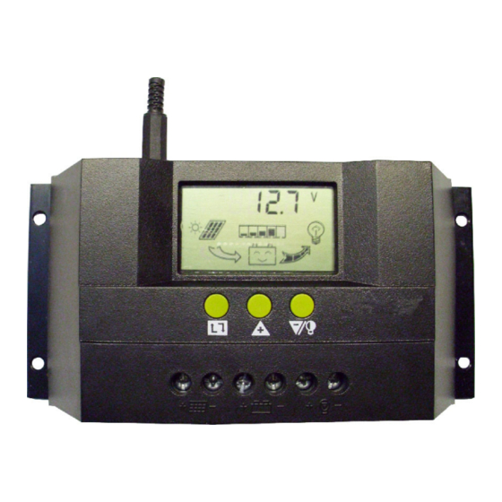
Intelligent Solar Charge Controller
User s M anual
Please read this instru ction carefully before using it.
SOLAR30 12V/24V
2 Installation Explanation
Installation
Get ready the related tools & cables. We suggest you choose the appropriate cables
to ensure the current density 4A/mm and this is good for reducing cable voltage
drop. Recommendation 30A using 10mm cable 50A using 16 mm cable.
Check whether installation
place accords with the relative
safety rules. Please avoid installing
and using the controller under
the following conditions: wet,
dusty places or places with
ammable and explosive gases.
Install the controller at the
vertical plane. Please refer to
chapter 5 for more d etailed info
about the spacing between the
installing holes. In order to make
the controller have good t h ermal
dissipation, please spare10cm
above & below the controller.
As shown as the right gure, connect the loads, battery and solar panels with the
controller in order. Pay attention to connect the loads, battery and solar panels right.
Plug the external thermal sensor into the interface of the thermal-sensor
of the controller.
Disassemble: To avoid the accident, please dismantle the solar panels, battery, loads
from the controller in order .
Attention: Connecting the battery reversed will not damage the controller, but will
cause safety risk on your loads.
2 . Explanation of button function:
:Interfaces circular toggling button. Use this button can realize the toggling circularly
among the interfaces. The circular order is as follows: as shown as gure 1.
: Parameter adjusting'+'+ button. Besides, under parameter review condition, press
this button for over 5 seconds, and all the parameters will recover to the ex-work
setting state.
:Parameter adjusting'-'button. Besides, at the main interface, this button can turn
or turn o the load.
13 .0
28
V
Battery voltage
battery
(main interface)
temperature
24
13 .8
LOAD O N
V
h
P V O F F
Load working
ceasing charging
state
voltage
3. Parameter review and setting:
After the controller electri es right, it will enter into the displaying interface of
battery voltage. This interface is the main interface of the controller. P ress
button to go through the interfaces of the following parameters. If the interface
can be reset, press button
interface starts to icker), then it enters into the setting interface of this parameter.
After nishing setting, press button for long to exit the setting interface, and the
number stops ickering.
AUTO WORK
2
2
2
Controller
Temperature
sensor
interface
Solar panels
Battery
20.0
20.0
LOAD
P V
A
A
solar panels
load discharging
generating current
current
1 2.6
1 0 .7
V
V
LOAD O N
LOAD
OF F
recovery v oltage
low voltage
protection poin
for long(
5 seconds, and the number on the
This controller is a kind of intelligent and multifunctional solar
charge controller. These serial products adopt customized LCD display
screen, which makes the operation on the interface rather convenient.
All the controlling parameters can be reset exibly to satisfy your di erent
needs. This controller has the following features:
1
1. Explanation of LCD Graphic Symbol
DC load
on the left
3
3.1 Battery voltage review
As shown as the right gure, the displaying number is the
present battery voltage.
This interface is the main interface, and it shows the
charging & discharging state, battery capacity and
battery voltage.
on
3.2 Load ON/OFF controlling
999
At the battery voltage review
P V
Ah
interface, you can press button
to turn on or turn o the load, while
accumulative
generating AH
this button does not have this function at other interfaces.
990
LO AD
Ah
3.3 Environmental temperature review
Be used for the temperature compensation when the
accumulative
battery ceases charging.
discharging AH
As shown as the right gure, the displaying number is the
surrounding environmental temperature of the controller.
3.4 Review the generating current of solar panels
As shown as the right gure, the displaying number is the
generating current of solar panels.
5
1 Product intr oduction
Visual LCD graphic symbol
Brief key operation
Grade auto switch of system voltage
Intelligent PWM Charging Mode
Auto temperature compensation
Adjustable charging & discharging parameter
Settable working modes of loads
Accumulative function of charging & discharging AH
Protection for battery back discharging
Protection for battery low voltage
Overloading & short-circuit protection
Battery reversed protection
Delayed auto restart after overloading protection
3. Operation
stop supplying power for loads
supplying power for loads,
no current in load loop
having current in load loop
load icon
solar panels icon
load light controlling icon
load timing controlling icon
stop charging for battery
charging for battery at full speed
oat charging for battery
normal working state of system
abnormal working state of system
battery capacity display
battery icon
1 2.5
2
4
1 2.5
V
1 2.5
V
V
28
27 .0
P V
A
6
Advertisement

Related Manuals for Efitron SOLAR30


Summary of Contents for Efitron SOLAR30
- Page 1 Protection for battery low voltage Overloading & short-circuit protection Please read this instru ction carefully before using it. Battery reversed protection Delayed auto restart after overloading protection SOLAR30 12V/24V AUTO WORK 2 Installation Explanation 3. Operation Installation Get ready the related tools & cables. We suggest you choose the appropriate cables 1.
- Page 2 Other exceptional conditions: Please contact the distributor or manufacturer. voltage, the controller will recover to supply power for load, and enter into the working state. Product Parameter model model SOLAR30 SOLAR30 parameter parameter rated working voltage 12V/24V installable maximum cable...
Need help?
Do you have a question about the SOLAR30 and is the answer not in the manual?
Questions and answers