
Subscribe to Our Youtube Channel
Related Manuals for PowMr POW-LVM2K-12V

Summary of Contents for PowMr POW-LVM2K-12V
- Page 1 POW-LVM2K-12V POW-HVM2K-12V POW-LVM3K-12V POW-HVM3K-12V INVERTER CHARGER User Manual...
-
Page 2: Table Of Contents
TABLE OF THE CONTENT GENERAL INFORMATION..............4 INTRUDUCTION..................5 Basic System Architecture............5 Instruction To Working Mode............5 PRODUCT OVERVIEW................6 Top View....................6 Real View.....................7 OPERATION....................8 Operation And Display Panel............9 LCD Display Icons................10 LCD Setting..................12 Fault Reference Code..............17 SPECIFICATIONS................. 18 DIMENSIONS..................20... - Page 3 ► Important Safety Instructions ◄ Please save these instructions This manual contains important safety, installation, and operating instructions for the inverter. The following symbols are used throughout the manual: Indicates a potentially dangerous condition. Use extreme caution when WARNING performing this task. Indicates a critical procedure for safe and proper operation of the inverter.
- Page 4 ■ Battery Safety ● Do NOT let the positive (+) and negative (-) terminals of the battery touch each other. ● Use sealed Lead-Acid, Flooded, Gel, AGM, Lithium or Calcium batteries which must be deep cycle. ● Explosive battery gases may be present while charging. Be certain there is enough ventilation to release the gases.
-
Page 5: General Information
● Multiple electronic protections ■ Pure Sine Wave The PowMr Power Inverters output a pure sine wave similar to the waveform of the grid power. In a pure sine wave, the voltage rises and falls in a smooth fashion with very low harmonic distortion and cleaner utility-like power. -
Page 6: Intruduction
IN TRODU CTION ■ Basic System Architecture ■ Instruction to working mode Inversion priority mode ● In case of normal battery voltage, the inverter operates under inversion mode and load power is supplied by battery inversion; ● The system automatically switches to battery-powered mode if the battery is fully charged by solar energy or wind Energy through controller. -
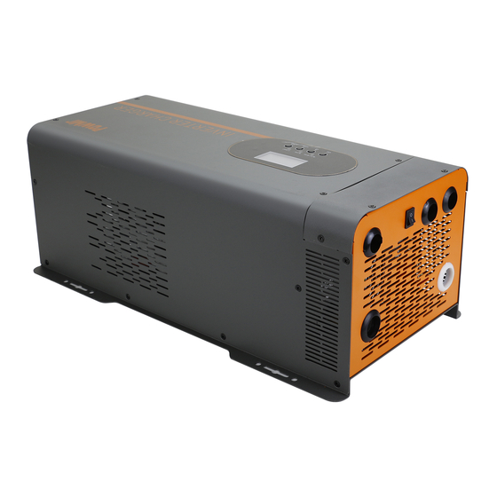
Page 7: Product Overview
Electric supply priority mode ● In case the load is powered by electric supply, the electric supply has to pass input protection device, And filter before supplying power to load in order to ensure power stability, it can be also charge the battery(determined By charging mode) ●... -
Page 9: Operation
OPERATION ■ Battery Charging Stages ● Bulk Stage: The charger will supply constant current until the battery voltage reaches the ● boost voltage: The software will calculate the time charging began up until the battery voltage reaches 0.3V below the boost voltage. It uses this time to as TO and T0x1 0 = T1. Boost Stage: The charger will supply constant voltage and reduce the current slowly through this stage. -
Page 21: Dimensions
DIM EN SION S ■ 2000W/3000W... - Page 22 Tel/Fax: +86 755-28219903 Email: aftersale@ysolartech.com Web: www.ysolartech.com Add: Henggang Street, Longgang District, Shenzhen, Guangdong, China...
Need help?
Do you have a question about the POW-LVM2K-12V and is the answer not in the manual?
Questions and answers