Table of Contents
Advertisement
Quick Links
D017-0025-301-01 IM500-SM500 Installation Guide
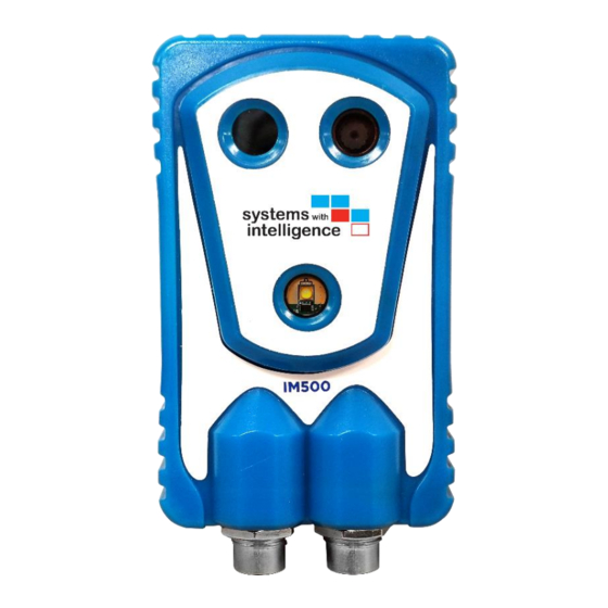
IM500/SM500
– Industrial IoT Module
2020.08.10
Installation Guide
support@SystemsWithIntelligence.com
www.SystemsWithIntelligence.com
Note: Please read this manual thoroughly before operating this unit and retain it for future reference.
1
www.SystemsWithIntelligence.com
support SystemsWithIntelligence.com
© 2020 Systems With Intelligence. All rights reserved.
Advertisement
Table of Contents

Subscribe to Our Youtube Channel
Related Manuals for Systems With Intelligence IM500

Summary of Contents for Systems With Intelligence IM500
- Page 1 D017-0025-301-01 IM500-SM500 Installation Guide IM500/SM500 – Industrial IoT Module 2020.08.10 Installation Guide support@SystemsWithIntelligence.com www.SystemsWithIntelligence.com Note: Please read this manual thoroughly before operating this unit and retain it for future reference. www.SystemsWithIntelligence.com support SystemsWithIntelligence.com © 2020 Systems With Intelligence. All rights reserved.
- Page 2 We have checked the contents of this manual against the hardware and software described. However, deviations from the description cannot be completely ruled out. Systems With Intelligence shall not be liable for any errors or omissions contained herein or for consequential damages in connection with the furnishing, performance, or use of this material.
-
Page 3: Federal Communications Commission Radio Frequency Interference Statement
This product contains no user-serviceable parts. Attempted service by unauthorized personnel shall render all warranties null and void. Changes or modifications not expressly approved by Systems With Intelligence Inc. could void the user’s authority to operate the equipment. Should this device require service please contact Systems With Intelligence. -
Page 4: Important Safety Instructions
10. To prevent damage from water leakage when installing a mount outdoors on a roof or wall, apply sealant around the bolt holes between the mount and mounting surface. 11. Only use replacement parts recommended by Systems With Intelligence. 12. Avoid aiming the camera directly to bright objects (e.g. sun) as this may damage the image sensor and thermal sensor of the camera. -
Page 5: Table Of Contents
Step 2: Junction box electrical connections ..................8 Step 3: Mounting the arm ........................10 Step 4: Connecting the power ......................12 Hardware interface connections ....................... 12 Optional: External Antenna ......................... 13 www.SystemsWithIntelligence.com support SystemsWithIntelligence.com © 2020 Systems With Intelligence. All rights reserved. -
Page 6: Introduction
Please note that each item can be order individually. 1. Mounting Arm (p/n SM-A01); you need one arm for each camera. 2. IM500 IoT module– visual and thermal camera or SM500 IoT Modbus Sensors module. 3. Power cable (p/n PCSM-MF4P-10); you need one power cable for each camera. -
Page 7: Installation Instructions
The junction box can be mounted on a flat surface using the included brackets. You can order optional brackets to mount the box on a pole. The dimensions of the enclosure are presented in Figure 6-1. Figure 6-1 Dimensions Junction Box www.SystemsWithIntelligence.com support SystemsWithIntelligence.com © 2020 Systems With Intelligence. All rights reserved. -
Page 8: Step 2: Junction Box Electrical Connections
D017-0025-301-01 IM500-SM500 Installation Guide 6.2 Step 2: Junction box electrical connections The internal components of the junction are presented in Figure 6-2. Figure 6-2 Junction box connections www.SystemsWithIntelligence.com support SystemsWithIntelligence.com © 2020 Systems With Intelligence. All rights reserved. - Page 9 • Typical current: 0.6A • Maximum current: 3A; limited by internal breaker. The junction box provides power to up to five IM500/SM500 units through the 4-pin connectors located at the bottom. The signals are shown in Table 6-1. Table 6-1 Power Connector: Front View...
-
Page 10: Step 3: Mounting The Arm
2. Mount the base (1) - you must mount this plate on the wall or pole. See dimensions in Figure 6-4 or Figure 6-6. 3. Mount the camera cradle (3) on the back of the IM500/SM500 using the camera mounting screw (5). Do not assemble the arm, proceed to the next section. - Page 11 D017-0025-301-01 IM500-SM500 Installation Guide Figure 6-5 Arm, base and cradle (v2) Figure 6-6 Mounting base dimensions (v2) www.SystemsWithIntelligence.com support SystemsWithIntelligence.com © 2020 Systems With Intelligence. All rights reserved.
-
Page 12: Step 4: Connecting The Power
2. Turn on the breaker in the junction box if not already on. Verify that the LED (light) of the power supply inside the box is on. 3. Connect the IM500 power cable (4-pin connector at both ends) to the junction box. It is possible to extend the power cable by daisy-chaining cables. -
Page 13: Optional: External Antenna
SMA Male connector. The connector must be connected to the top of the IM500/SM500 and the antenna must be mounted using the self-adhesive tape. www.SystemsWithIntelligence.com support SystemsWithIntelligence.com © 2020 Systems With Intelligence. All rights reserved. - Page 14 D017-0025-301-01 IM500-SM500 Installation Guide Figure 6-8 Dimensions IM500 www.SystemsWithIntelligence.com support SystemsWithIntelligence.com © 2020 Systems With Intelligence. All rights reserved.
- Page 15 D017-0025-301-01 IM500-SM500 Installation Guide www.SystemsWithIntelligence.com support SystemsWithIntelligence.com Systems With Intelligence Inc. Sales Inquiries: © 2020 Systems With Intelligence. All rights reserved. sales@SystemsWithIntelligence.com 6889 Rexwood Road, Unit #9 Mississauga, Ontario, CANADA...
Need help?
Do you have a question about the IM500 and is the answer not in the manual?
Questions and answers