Table of Contents
Advertisement
Quick Links
IM500-SM500 User's Guide [D017-0025-200-02]]
IM500-SM500
– IoT Module
2021.03.09 [D017-0025-200-02]
User's Guide
support@SystemsWithIntelligence.com
www.SystemsWithIntelligence.com
Note: Please read this manual thoroughly before operating this unit and retain it for future reference.
1
support SystemsWithIntelligence.com
www.SystemsWithIntelligence.com
© 2020 Systems With Intelligence. All rights reserved.
Advertisement
Table of Contents

Subscribe to Our Youtube Channel
Related Manuals for Systems With Intelligence IM500

Summary of Contents for Systems With Intelligence IM500
- Page 1 IM500-SM500 User’s Guide [D017-0025-200-02]] IM500-SM500 – IoT Module 2021.03.09 [D017-0025-200-02] User’s Guide support@SystemsWithIntelligence.com www.SystemsWithIntelligence.com Note: Please read this manual thoroughly before operating this unit and retain it for future reference. support SystemsWithIntelligence.com www.SystemsWithIntelligence.com © 2020 Systems With Intelligence. All rights reserved.
- Page 2 We have checked the contents of this manual against the hardware and software described. However, deviations from the description cannot be completely ruled out. Systems With Intelligence shall not be liable for any errors or omissions contained herein or for consequential damages in connection with the furnishing, performance, or use of this material.
- Page 3 Changes or modifications not expressly approved by Systems With Intelligence Inc. could void the user’s authority to operate the equipment. Should this device require service please contact Systems With Intelligence. support SystemsWithIntelligence.com www.SystemsWithIntelligence.com © 2020 Systems With Intelligence. All rights reserved.
-
Page 4: Table Of Contents
IM500-SM500 User’s Guide [D017-0025-200-02]] 1 Table of Contents Terminology ................................... 7 Read Me First ..................................8 Introduction – IM500 and SM500 Overview ......................9 First Time Setup .................................. 11 Initial Administrator..........................11 Setup Operator ............................12 Registration ..............................12 Administration Tasks ................................. 14 Add New Device via ID ..........................14... - Page 5 SM500 Configuration ................................ 61 Introduction ..............................62 9.1.1 General Application ..........................62 9.1.2 Mapping ............................64 Stage 1: Add New SM500 Device......................65 Stage 2: Device Setup ..........................66 9.3.1 SM500 Setup Page ..........................66 support SystemsWithIntelligence.com www.SystemsWithIntelligence.com © 2020 Systems With Intelligence. All rights reserved.
- Page 6 Type: Gauge ..............................86 10.6 Type: Line chart (IM500) ..........................87 10.7 Type: Line chart (SM500) ..........................88 10.8 Type: Write box (SM500) ..........................90 10.9 Type: Snapshot (IM500) ...........................91 10.10 Export to file ............................92 support SystemsWithIntelligence.com www.SystemsWithIntelligence.com © 2020 Systems With Intelligence. All rights reserved.
-
Page 7: Terminology
World Wide Web. Currently supported Chrome and Firefox. LAN / WAN Local Area Network / Wide Area Network • RS485 Serial communication using 2 or 4 wires that allows daisy-chaining multiple • electronic devices. support SystemsWithIntelligence.com www.SystemsWithIntelligence.com © 2020 Systems With Intelligence. All rights reserved. -
Page 8: Read Me First
Section 7 - Everyday operation You will learn how to do the everyday tasks and use all the features of the system. Section 8 – IM500 Configuration Instructions for configuring the IM500 for temperature measurements and thermal alarm reporting. Section 9 – SM500 Configuration Step-by-step instructions to configure the SM500 to monitor and report measurements from your installation. -
Page 9: Introduction - Im500 And Sm500 Overview
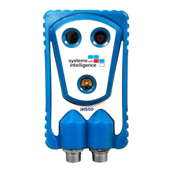
IM500-SM500 User’s Guide [D017-0025-200-02]] 4 Introduction – IM500 and SM500 Overview The IM500 Industrial IoT Module monitors and collects asset health data from remote sites. Thermal monitoring mitigates the risks of failure from overheating assets and connection points. Analytics detect anomalies and provide automatic warnings. - Page 10 • Bi-directional data flow. • INTEGRATION Data collected by IM500 and SM500 can be integrated with a SCADA system or other asset • monitoring software, by using the optional ISG500 (Intelligent Sensor Gateway). UTILITY GRADE Designed for the harsh conditions found in electric power environments.
-
Page 11: First Time Setup
URL may change in the future), not by sending an email. The person who submits this request would be the initial administrator and is responsible for adding new Administrator and Operator accounts. There can be multiple administrators. support SystemsWithIntelligence.com www.SystemsWithIntelligence.com © 2020 Systems With Intelligence. All rights reserved. -
Page 12: Setup Operator
5-2. The e-mail contains an invitation code and a website link – arrow 2. Click the link and your web browser will open the “New user log-in” page as seen in Figure 5-3. Figure 5-2 Registration e-mail support SystemsWithIntelligence.com www.SystemsWithIntelligence.com © 2020 Systems With Intelligence. All rights reserved. - Page 13 Troubleshooting: If you do not receive the invitation e-mail in the next 24 hours please contact SWI for assistance. Also check your “Spam” folder; the e-mail may be filtered out. support SystemsWithIntelligence.com www.SystemsWithIntelligence.com © 2020 Systems With Intelligence. All rights reserved.
-
Page 14: Administration Tasks
IM500-SM500 User’s Guide [D017-0025-200-02]] 6 Administration Tasks The Administrator is responsible for activating new IM500/ SM500 IoT units and for adding new users to the organization. The instructions in this section can be performed only by an Administrator. 6.1 Add New Device via ID One of the first task of an Administrator is to add new devices to the Dashboard. -
Page 15: Add New Device Via Camera Scanning
3. Press the “Allow” button and the pop-up dialog box will close. The video stream will be displayed at the right of the window under the “Video device 1” drop-down. support SystemsWithIntelligence.com www.SystemsWithIntelligence.com © 2020 Systems With Intelligence. All rights reserved. -
Page 16: User Profile - Operator Page
IM500-SM500 User’s Guide [D017-0025-200-02]] 4. Place the IM500/SM500 unit with the label facing the camera and held it until the image is in focus. After a successful scan the video stream stops and the ID is placed in the “Device ID” field. - Page 17 11. Press on the account link (red) to configure or cancel invitation – details in section 6.6. 12. Press on the account link (blue) to configure permissions – details in section 6.7. support SystemsWithIntelligence.com www.SystemsWithIntelligence.com © 2020 Systems With Intelligence. All rights reserved.
-
Page 18: Add New Users
5. Note: Press the “x” to remove this e-mail field and no invitations is sent. An invitation can be canceled later using the instructions in section 6.6. support SystemsWithIntelligence.com www.SystemsWithIntelligence.com © 2020 Systems With Intelligence. All rights reserved. -
Page 19: Pending Invitation: Update Or Delete
Delete invitation - Figure 6-5 (arrow 7) press the “Delete Invitation” button to cancel the creation of the account. Press the “Back” button to return to “User Settings” page. support SystemsWithIntelligence.com www.SystemsWithIntelligence.com © 2020 Systems With Intelligence. All rights reserved. -
Page 20: Operator Account Management
Please note that the following operations cannot be undone. In Figure 6-6 Area B, there are two special functions: “Delete User” - press this button to remove this account. • “Promote to Administrator”- press this button to grant administrator rights to this account. • support SystemsWithIntelligence.com www.SystemsWithIntelligence.com © 2020 Systems With Intelligence. All rights reserved. -
Page 21: Accept Invitation
In Figure 6-7 is shown the Administrator’s page and where the pending invitation is located. Click “Accept” button to be part of the organization listed to the right (arrow 2). Click the ”Reject” button to deny the invitation. Figure 6-7 Accept Invitation support SystemsWithIntelligence.com www.SystemsWithIntelligence.com © 2020 Systems With Intelligence. All rights reserved. -
Page 22: User Activity Logs
9. Activity – displays details of the specific activity. Typical activities include: A. Logged in/ out. B. Update settings. C. Delete alarms. 10. Press the “Back” button to return to main window. support SystemsWithIntelligence.com www.SystemsWithIntelligence.com © 2020 Systems With Intelligence. All rights reserved. -
Page 23: Set Logo
2. Select the “Company Logo.png” file. The picture must no larger than 1 Mbyte and be in format jpg, jpeg, png or bmp. 3. Press the “Open” button and you the dialog box will close. 4. Press the “Submit” button and the web page will update. support SystemsWithIntelligence.com www.SystemsWithIntelligence.com © 2020 Systems With Intelligence. All rights reserved. -
Page 24: Enable 2-Factor Authentication
2. A verification code is sent to your e-mail. You will receive a new code for each new log-in. 3. Enter the “Verification Code”. 4. Press the “Validate” button. support SystemsWithIntelligence.com www.SystemsWithIntelligence.com © 2020 Systems With Intelligence. All rights reserved. -
Page 25: Contact Us
For a quick and convenient way to send us a message use the “Contact Us” button on the top right of the window. Fill in the form displayed in Figure 6-12: support SystemsWithIntelligence.com www.SystemsWithIntelligence.com © 2020 Systems With Intelligence. All rights reserved. -
Page 26: Snapshot Limit Alert
The current usage is displayed on the Dashboard and described in Section 7.3. The temperature measurements and alarm monitoring will continue to operate but no snapshots will be recorded. Figure 6-13 Snapshot Limit Alert support SystemsWithIntelligence.com www.SystemsWithIntelligence.com © 2020 Systems With Intelligence. All rights reserved. -
Page 27: Notifications Of Organization Change
6.14 Notifications of Organization Change All administrators receive e-mail notifications if a user is leaving or if a new user is joining your organization (see Figure 6-15). Figure 6-15 Organization change notification support SystemsWithIntelligence.com www.SystemsWithIntelligence.com © 2020 Systems With Intelligence. All rights reserved. -
Page 28: Everyday Operation
Figure 7-2. Best practice: Is good practice to use Operator credentials for day-to-day operations even if you are an Administrator. Figure 7-1 Log-in support SystemsWithIntelligence.com www.SystemsWithIntelligence.com © 2020 Systems With Intelligence. All rights reserved. -
Page 29: List All Devices - Main Page
3. Click on the “All Devices” button to zoom out and show all units. Use the “<” and “>” to circle until you find the specific unit to display. Pressing “All Devices” zooms out the map and displays all units. support SystemsWithIntelligence.com www.SystemsWithIntelligence.com © 2020 Systems With Intelligence. All rights reserved. -
Page 30: Unit Status
Figure 7-3 Unit Status The Summary will turn red when there is an active alarm (closed digital input or output), license expiry soon (within 3), or the snapshots limit is reached. support SystemsWithIntelligence.com www.SystemsWithIntelligence.com © 2020 Systems With Intelligence. All rights reserved. -
Page 31: Device Page
C. Area C – The latest snapshots; detailed description in section 7.5.4 and 7.5.5. D. Area D – The latest temperature measurements and status of the Digital Input/output – see section 7.7. Figure 7-4 Device Page support SystemsWithIntelligence.com www.SystemsWithIntelligence.com © 2020 Systems With Intelligence. All rights reserved. -
Page 32: Title, Quota And Setup Buttons
10. Select the measuring unit: Celsius or Fahrenheit. 11. Check the “Live Update” box to receive data from the site continuously, according to the polling interval and update time. Figure 7-5 Title and Setup Buttons support SystemsWithIntelligence.com www.SystemsWithIntelligence.com © 2020 Systems With Intelligence. All rights reserved. -
Page 33: Device Status - Ping Device
7.5.1 Device Status - Ping Device The Dashboard gives you the ability to check the status of the IM500 unit. In the “Device Page” click the ping icon located at the right of the name of the unit – arrow 1 in Figure 7-6. -
Page 34: Historical Data
File” dialog box will open – see Figure 7-8. Click the “Save File” box and click OK. Browse to the folder where to save the file and click OK. support SystemsWithIntelligence.com www.SystemsWithIntelligence.com © 2020 Systems With Intelligence. All rights reserved. - Page 35 "Feb 26, 2019, 1:27:35 PM",-10.48,-2.09,-6.24,-10.61,-1.08,-5.55,-9.88,-1.41,-4.6,-3.08,9.32,6.15,- "Feb 26, 2019, 1:32:36 PM",-10.31,-2.87,-6.57,-10.05,-2.03,-5.76,-9.42,-2.39,-5.1,-3.14,8.69,5.54,- "Feb 26, 2019, 1:37:34 PM",-12.48,-3.11,-7.58,-11.56,-2.48,-6.53,-10.95,-2.75,-5.59,-2.87,8.55,5.4,- "Feb 26, 2019, 1:42:36 PM",-15.66,-4.64,-9.72,-16.35,-3.94,-8.74,-15.63,-4.7,-8.32,-4.34,6.55,3.48,- "Feb 26, 2019, 1:47:34 PM",-20.98,-4.95,-12.39,-19.95,-4.15,-10.47,-18.55,-4.89,-9.5,-4.64,6.36,3.08,- Figure 7-9 CSV Data support SystemsWithIntelligence.com www.SystemsWithIntelligence.com © 2020 Systems With Intelligence. All rights reserved.
-
Page 36: Graph Temperature Difference
Figure 7-11 Temperature Comparison To return to temperature viewing, click on the “Box Selection” Figure 7-7 arrow 3 and follow instructions in Figure 7-12. Figure 7-12 Box Selection: Temperature support SystemsWithIntelligence.com www.SystemsWithIntelligence.com © 2020 Systems With Intelligence. All rights reserved. -
Page 37: Thermal Snapshot
8. Download the image in “png” format. Press this button and a new dialog box will prompt you to select a location for the file; the file name includes the device ID and the timestamp. The file can be opened with a photo viewer (Paint). support SystemsWithIntelligence.com www.SystemsWithIntelligence.com © 2020 Systems With Intelligence. All rights reserved. -
Page 38: Visual Snapshot
The file can be opened with a photo viewer (Paint). 5. Shows the time stamp. 6. Press the “Take New Snapshot” button to take and retrieve a snapshot. Figure 7-14 Visual Snapshot support SystemsWithIntelligence.com www.SystemsWithIntelligence.com © 2020 Systems With Intelligence. All rights reserved. -
Page 39: Data And Digital I/O Status
4. Maximum temperature. 5. Average temperature. 6. This column indicates the current status of the digital input and output. 7. This column contains the time stamp of the last acquisition. support SystemsWithIntelligence.com www.SystemsWithIntelligence.com © 2020 Systems With Intelligence. All rights reserved. -
Page 40: Historical Alarm Triggers
10. This column displays the “Time stamp” of the alarm; you could click to sort them chronologically. 11. Click on the snapshot and the dialog box will display the picture taken. support SystemsWithIntelligence.com www.SystemsWithIntelligence.com © 2020 Systems With Intelligence. All rights reserved. -
Page 41: Digital I/O
4. Select the “Output Control”: open or close. In this example the output is already closed and open is selected. 5. Press the “Apply” button and the command will be sent. support SystemsWithIntelligence.com www.SystemsWithIntelligence.com © 2020 Systems With Intelligence. All rights reserved. -
Page 42: Gallery
1. Enter the date or press the calendar icon to select the desired date. 2. Press the search button. 3. Press the Back button to return to the Device page. Figure 7-18 Gallery support SystemsWithIntelligence.com www.SystemsWithIntelligence.com © 2020 Systems With Intelligence. All rights reserved. -
Page 43: Data Export
IM500-SM500 User’s Guide [D017-0025-200-02]] 7.9 Data Export On the “Data Export” page you can export the data of one or more IM500 devices. Figure 7-19 Data Export Navigation – follow Figure 7-19: 1. Devices – click on “Select All“ or select individual devices as shown in (A). -
Page 44: E-Mail Alarm Notification
3. This section contains the “Description”, the “Device” and the “Condition”. 4. This section contains a link to the image that you could see by clicking on it. support SystemsWithIntelligence.com www.SystemsWithIntelligence.com © 2020 Systems With Intelligence. All rights reserved. -
Page 45: Im500 Configuration
IM500-SM500 User’s Guide [D017-0025-200-02]] 8 IM500 Configuration In this section you will learn how to customize and fine tune the IM500 configuration to meet the needs of your application. There are two types of configuration: 1. One-time settings include: change the password (optional) and set the location. - Page 46 IM500-SM500 User’s Guide [D017-0025-200-02]] Figure 8-1 Device Setup Figure 8-2 Access Permission support SystemsWithIntelligence.com www.SystemsWithIntelligence.com © 2020 Systems With Intelligence. All rights reserved.
-
Page 47: Edit Device List
Figure 8-4 to edit the tree-view. Press the “Edit Device List” button – arrow 2 in Figure 8-3 and the “Edit Device List” page is opened. Note: Empty labels are not displayed in in the tree-view. support SystemsWithIntelligence.com www.SystemsWithIntelligence.com © 2020 Systems With Intelligence. All rights reserved. -
Page 48: Change Password
1. Click the “User Settings” on the left menu to view the User Profile page. 2. Enter the current password. 3. Enter the new password minimum 8 characters. 4. Retype the new password. 5. Press the “Update Password” button. support SystemsWithIntelligence.com www.SystemsWithIntelligence.com © 2020 Systems With Intelligence. All rights reserved. -
Page 49: Ircam Setup
IM500-SM500 User’s Guide [D017-0025-200-02]] 8.4 Thermal Sensor Setup The main functionality of the IM500 unit is based on measuring, monitoring and analyzing the temperatures in specific areas, named “Thermal Boxes” – maximum six. In this section you will learn how to draw, name and configure the thermal boxes. - Page 50 The visual snapshot can be used as reference for drawing the thermal boxes. Optional: you can press the “Take New Snapshot” button to retrieve a new image. Figure 8-6 Radiometry Parameters support SystemsWithIntelligence.com www.SystemsWithIntelligence.com © 2020 Systems With Intelligence. All rights reserved.
- Page 51 5. Target Emissivity is the emissivity of the source. 6. Air Temperature is used to compute the atmospheric transmission. 7. Target Distance measured from IM500 to the source; used to compute the atmospheric transmission. 8. Window Transmission - fraction of IR radiation passed through the window.
-
Page 52: Setup Alarms And Events
The thermal configuration is closely related to the equipment that is monitored. It is very important that you have a good understanding of the system you are monitoring and you should configure the IM500 based on that information. In this section you will learn how to configure the thermal monitoring. There are three types of alarms that can be configured. -
Page 53: Absolute Comparison
7. Type the value of the temperature or use the up/down buttons to adjust. 8. Select the measuring unit: C or F. 9. Select Both, Visual or IR snapshot. support SystemsWithIntelligence.com www.SystemsWithIntelligence.com © 2020 Systems With Intelligence. All rights reserved. -
Page 54: Relative Comparison
2 by 10C. These are the configuration steps – follow Figure 8-9 1. Type a name for this alarm; “b1 > b2”. 2. Optional: add a detailed description; “Box 1 exceeds box 2 by 10C”. support SystemsWithIntelligence.com www.SystemsWithIntelligence.com © 2020 Systems With Intelligence. All rights reserved. - Page 55 Optional: you can configure the system to send one or more e-mails when this alarm is triggered. Press the “+” sign (arrow 12) and type the e-mail address in field pointed by arrow 13. For multiple e-mails press the “+” again and type the new recipient. support SystemsWithIntelligence.com www.SystemsWithIntelligence.com © 2020 Systems With Intelligence. All rights reserved.
-
Page 56: Relative Delta Comparison
3. Click on the “Condition type” drop-list and select “Relative Delta”. 4. Select “avg” in the drop-box list. Also available: “min” and “max”. 5. Select the first box of interest: Box 1. 6. Select the second box: Box 2. support SystemsWithIntelligence.com www.SystemsWithIntelligence.com © 2020 Systems With Intelligence. All rights reserved. - Page 57 For multiple e-mails press the “+” again and type the new recipient. 13. Press the “Save” button to preserve this configuration or press “Cancel” to discard (no alarm will be saved). support SystemsWithIntelligence.com www.SystemsWithIntelligence.com © 2020 Systems With Intelligence. All rights reserved.
-
Page 58: Three Way Delta
7. Select the third box: Box 3. 8. Select the condition: “greater than” or “less than” in the drop-down list. 9. Type the value of the temperature or use the up/down buttons to adjust. support SystemsWithIntelligence.com www.SystemsWithIntelligence.com © 2020 Systems With Intelligence. All rights reserved. -
Page 59: Configure Digital Input Alarm
“+” again and type the new recipient. 8.7 Configure Digital Input Alarm The digital input must be wired to the IM500 before it is configured. In this example there is a micro-switched installed at the South Gate and is connected to DI1 (digital input 1). -
Page 60: Configure Interval Snapshot
Figure 8-13 Configure Interval Snapshot 8.9 Configure Daily Snapshot This configuration instructs the IM500 to take a snapshot every day at a specific time. 1. Type a name to identify this event. 2. Optional: type a description. 3. Scheduled time: click on the drop down list and select the time. -
Page 61: Sm500 Configuration
You must complete four configuration stages in order to have a functional data concentrator: 1. Add new SM500 - section 9.2. 2. Configure communication - section 9.3.2. 3. Configure Points - section 9.4. 4. Setup Alarms and Events – section 9.5. support SystemsWithIntelligence.com www.SystemsWithIntelligence.com © 2020 Systems With Intelligence. All rights reserved. -
Page 62: Introduction
For the purpose of this manual a simple water reservoir installation is used to guide you through the configuration process. The diagram of this installation is shown in Figure 9-2. Figure 9-2 General Application support SystemsWithIntelligence.com www.SystemsWithIntelligence.com © 2020 Systems With Intelligence. All rights reserved. - Page 63 PLC internal Digital Status Coil 1 that indicates pump is ON/OFF PLC output controls the fan of PLC internal Digital Status Coil 2 control the control house that indicates light is ON/OFF support SystemsWithIntelligence.com www.SystemsWithIntelligence.com © 2020 Systems With Intelligence. All rights reserved.
-
Page 64: Mapping
House temperature 16-bit unsigned Holding register Battery state 1-bit Section 9.4.3 Discrete Input Main power state 1-bit Discrete Input Pump control 1-bit Coil Section 9.4.2 Fan control 1-bit Coil support SystemsWithIntelligence.com www.SystemsWithIntelligence.com © 2020 Systems With Intelligence. All rights reserved. -
Page 65: Stage 1: Add New Sm500 Device
5. Click the “Submit” button and the new unit will be listed in the “Device List” page. Once you complete this task the device is shown on the “List All Devices” page and you could proceed to section 9.3. support SystemsWithIntelligence.com www.SystemsWithIntelligence.com © 2020 Systems With Intelligence. All rights reserved. -
Page 66: Stage 2: Device Setup
3. Digital IO button – see section 9.6. 4. Device Setup button – see section 9.3.2. 5. Modbus Setup button – see section 9.4. Figure 9-4 SM500 Setup Page support SystemsWithIntelligence.com www.SystemsWithIntelligence.com © 2020 Systems With Intelligence. All rights reserved. -
Page 67: Communication Setup
‘X’. 8. Press the Save button to preserve the settings. Press the Back button to discard the changes and return to previous page. Figure 9-5 Device Setup support SystemsWithIntelligence.com www.SystemsWithIntelligence.com © 2020 Systems With Intelligence. All rights reserved. -
Page 68: Stage 3: Modbus Setup
1 bit discrete input (0x02, base address 10001) 16 bit holding register signed or unsigned (0x03, base address 40001) 16 bit input register signed or unsigned (0x04, base address 30001) support SystemsWithIntelligence.com www.SystemsWithIntelligence.com © 2020 Systems With Intelligence. All rights reserved. - Page 69 Confirm – press this button to preserve this configuration and return to previous page. You • must press the “Save” button on the Point Setup page for the configuration to take effect. support SystemsWithIntelligence.com www.SystemsWithIntelligence.com © 2020 Systems With Intelligence. All rights reserved.
-
Page 70: Coil Register [1 - 9999]
7. Scaling Addition – not available for this type. 8. Cancel: press this button to discard the configuration and return to previous page. 9. Confirm: press this button to save the configuration. Figure 9-7 Configure Coil support SystemsWithIntelligence.com www.SystemsWithIntelligence.com © 2020 Systems With Intelligence. All rights reserved. -
Page 71: Discrete Input Registers [ 10001 - 19999]
8. Cancel: press this button to discard the configuration and return to previous page. 9. Confirm: press this button to save the configuration. Figure 9-8 Configure Discrete Input support SystemsWithIntelligence.com www.SystemsWithIntelligence.com © 2020 Systems With Intelligence. All rights reserved. -
Page 72: Input Registers [30001 - 39999]
8. Scaling Addition: default value 0. This coefficient is used to scale the displayed value in the “Visualization” page. 9. Cancel: discard and close. 10. Confirm: saves the configuration. Figure 9-9 Configure Analog Input Register support SystemsWithIntelligence.com www.SystemsWithIntelligence.com © 2020 Systems With Intelligence. All rights reserved. -
Page 73: Holding Registers [40001 - 49999]
8. Scaling Addition: default value 0. This coefficient is used to scale the displayed value in the “Visualization” page. 9. Cancel: discard and close. 10. Confirm: saves the configuration. Figure 9-10 Configure Holding Register support SystemsWithIntelligence.com www.SystemsWithIntelligence.com © 2020 Systems With Intelligence. All rights reserved. -
Page 74: Stage 4: Setup Alarms And Events
4. Configure DI – instructions in section 9.5.3 The header of the list contains the following columns: 5. Name – identifier of function and/or location. 6. Description – additional information to complement the name. support SystemsWithIntelligence.com www.SystemsWithIntelligence.com © 2020 Systems With Intelligence. All rights reserved. -
Page 75: Analog Alarm
9. Cancel: press this button to discard the configuration and return to previous page. 10. Save: press this button to confirm the settings. Figure 9-12 Configure Analog Alarm support SystemsWithIntelligence.com www.SystemsWithIntelligence.com © 2020 Systems With Intelligence. All rights reserved. -
Page 76: Binary Alarm
9. Cancel: press this button to discard the configuration and return to previous page. 10. Save: press this button to confirm the settings. Figure 9-13 Configure Binary Alarm support SystemsWithIntelligence.com www.SystemsWithIntelligence.com © 2020 Systems With Intelligence. All rights reserved. -
Page 77: Configure Di
10. Save: press this button to confirm the settings. Figure 9-14 Configure Digital Input 9.6 Digital I/O The configuration of the Digital I/O is detailed in section 7.7. support SystemsWithIntelligence.com www.SystemsWithIntelligence.com © 2020 Systems With Intelligence. All rights reserved. -
Page 78: Data Visualization
You select how to display data from multiple units and multiple sites. For example, you could customize a Data Visualization page to show measurements from three IM500 units on the same site: temperatures of phase A, B, C on bushings of Feeder 1 on the same line-chart as phase A, B, C on bushings of Feeder 2. - Page 79 1. Live Update – slide the button and data will be refreshed based on the polling rate. 2. IM500 only: select between Celsius and Fahrenheit. 3. Time range drop-down list selection: 1/ 2/ 12 hours, 1/ 2/ 4/ 7/ 14/ 30 days and Custom. This setting is changing the range for all tables and line-charts in the current dashboard.
-
Page 80: Start: New View
7. Press the newly created link and proceed to section 10.2. 8. Optional: you could click the edit icon to change the name of page. Also, you could click the trash icon to completely delete the page. support SystemsWithIntelligence.com www.SystemsWithIntelligence.com © 2020 Systems With Intelligence. All rights reserved. -
Page 81: Type: Display Box
10. Press the “Update” button to preserve the configuration and return to previous page. To discard the changes press the “Cancel” button. 11. Repeat steps 3 to 7 to add all measurements of interest. support SystemsWithIntelligence.com www.SystemsWithIntelligence.com © 2020 Systems With Intelligence. All rights reserved. - Page 82 1. Live Update – slide the button and data will be refreshed based on the polling rate. 2. IM500 only: select between Celsius and Fahrenheit. 3. Time range drop-down list selection: 1 hour to 30 days, days and Custom. This is selection applies for the entire page and affects only the table and the line-chart.
-
Page 83: Type: Table
9. Use the left-right arrow to navigate to previous/next tab. 10. Press the Update button to save the changes and return to main page. Press Cancel to discard the last changes. support SystemsWithIntelligence.com www.SystemsWithIntelligence.com © 2020 Systems With Intelligence. All rights reserved. - Page 84 In In Figure 10-6 is shown the Table view for the SM500 Water Level Monitor: 1. Select in the drop-down list the period that will be plotted. 2. Header: left column displays the acquisition date and time; right column shows the data. support SystemsWithIntelligence.com www.SystemsWithIntelligence.com © 2020 Systems With Intelligence. All rights reserved.
-
Page 85: Type: Digital I/O
7. Press “x” if you want to delete this entry. 8. Press the “Update” button to preserve the configuration and return to previous page. To discard the changes, press the “Cancel” button. support SystemsWithIntelligence.com www.SystemsWithIntelligence.com © 2020 Systems With Intelligence. All rights reserved. -
Page 86: Type: Gauge
9. Press the “+” icon to add a new configuration tab. 10. Press the left/right arrow to navigate to another tab. 11. Press “x” if you want to delete this entry. support SystemsWithIntelligence.com www.SystemsWithIntelligence.com © 2020 Systems With Intelligence. All rights reserved. -
Page 87: Type: Line Chart (Im500)
2. Enter the Name to be displayed for this graph (E.g. “Phase A+B+C”, “pump vs. water”) 3. Select “line chart” in the drop-down list based on the IoT type: IM500 or SM500. 4. Select in the “Device” drop-down list the unit that collects the data. -
Page 88: Type: Line Chart (Sm500)
Start by clicking the “Data Visualization” in the left menu and then click on the name of the page you created in section 10.1. Press the Edit button on the right menu (arrow 8 in Figure 10-4) then follow instructions in Figure 10-10: support SystemsWithIntelligence.com www.SystemsWithIntelligence.com © 2020 Systems With Intelligence. All rights reserved. - Page 89 In Figure 10-11 is shown the SM500 Water Tank Monitor line-chart view: 1. Place the mouse over the legend (top-left) and drag to a desired location. 2. Select in the drop-down list the period that will be plotted. support SystemsWithIntelligence.com www.SystemsWithIntelligence.com © 2020 Systems With Intelligence. All rights reserved.
-
Page 90: Type: Write Box (Sm500)
2. Press the “Write” button to send the value to the unit. A message will be displayed at the bottom of the page to show the result of the operation: Success or Error. The Error message is return when the value is set to “-1”. support SystemsWithIntelligence.com www.SystemsWithIntelligence.com © 2020 Systems With Intelligence. All rights reserved. -
Page 91: Type: Snapshot (Im500)
IM500-SM500 User’s Guide [D017-0025-200-02]] 10.9 Type: Snapshot (IM500) The Snapshot-IM500 view allows you to view the last shot side by side with other relatable data: temperatures in a line-chart, snapshot from other IM500. Figure 10-14 Configure: Snapshot Box Press the Edit button on the right menu (arrow 8 in Figure 10-4) then follow instructions Figure 10-14: 9. -
Page 92: Export To File
1. Press the “Export” button and the “Save” file dialog box will open. 2. Type the name of the file and select the location of the file. 3. Press the “Save” button and you will return to the main page. support SystemsWithIntelligence.com www.SystemsWithIntelligence.com © 2020 Systems With Intelligence. All rights reserved. - Page 93 IM500-SM500 User’s Guide [D017-0025-200-02]] Systems With Intelligence Inc. Sales Inquiries: 6889 Rexwood Road, Unit #9 sales@SystemsWithIntelligence.com Mississauga, Ontario, CANADA L4V 1R2 Product Support: support@SystemsWithIntelligence.com Tel: +1-289-562-0126 Fax: +1-289-562-0152 General Inquiries: info@SystemsWithIntelligence.com support SystemsWithIntelligence.com www.SystemsWithIntelligence.com © 2020 Systems With Intelligence. All rights reserved.
Need help?
Do you have a question about the IM500 and is the answer not in the manual?
Questions and answers