
Subscribe to Our Youtube Channel
Related Manuals for NORBIT WBMS

Summary of Contents for NORBIT WBMS
- Page 1 User and Technical Manual NORBIT GUI 10.4.3 TN-140075-9 WBMS Bathy Manual April 2020...
-
Page 2: Copyright Statement
WBMS 12003 iWBMSe 12006 iWBMSc 12005 iWBMS/STX 12004 iWBMSh/STX 12007 Release Notice This is the April 17, 2020 release of the NORBIT WBMS user and technical manual. 10.4.3 User Manual Contents April 17, 2020 Firmware: 5.2.1 Page 2 of 142... - Page 3 WBMS Sonar Head ..................... 17 iWBMS, iWBMSh, iWBMSe & STX Sonar Head and IMU .......... 17 Dry-End Overview ......................19 WBMS Sonar Interface Unit (SIU) ................19 iWBMS Sonar Interface Unit (SIU-I-NAV) ..............20 LED Status Indicators & Description ................21 SIU Aux Port ........................
- Page 4 Sky Plot ........................42 System Status ......................43 Subscribing to Marinestar .................... 44 Logging ........................45 TSS1 ..........................45 Main WBMS GUI Display ....................46 Sonar Settings Menus ....................46 View ..........................47 Backscatter Controls ....................48 Tx Pulse Settings ......................49 Advanced ........................
- Page 5 12005 iWBMSc / 12006 iWBMSe – Wet-end Dimensions – PN 24005/24018 ... 118 12003 WBMS – Wet-end Dimensions (PN 24003-ACDB)........... 119 12003 WBMS with 0.95° Tx – Wet-end Dimensions (PN 24003-ABDB) ..... 120 WBMS Sonar Interface Unit (SIU) Dimensions (PN 29024) ........121 Appendix D: Cable Pinout Diagrams ....................
- Page 6 Integrated WBMS – Entry Level (SurfMaster) iWBMSe Integrated WBMS – Compact (pre-mid-grade with STIM300) iWBMSc Integrated WBMS – Standard (mid-grade with WaveMaster) iWBMS Integrated WBMS – Pro (with top level OceanMaster) iWBMSh Light Emitting Diode MBES Multibeam Echosounder Sonar Network Time Protocol Positioning &...
-
Page 7: Technical Overview
Technical Overview The NORBIT Wide Band Multibeam Sonar (WBMS) is the most compact, high resolution, wide swath multibeam sonar available. With a dry-weight of less than 4.5kg (10lbs), beam widths of only 0.9° at 400kHz, and low power consumption, the stand-alone multibeam sonar easily mounts to a survey platform of any size and may be powered by a small battery (e.g. -
Page 8: How To Use This Manual
• The WBMS does not begin to beam steer until ± 30° from nadir. This results in lower incidence of depth error from the reduced beam width spreading as steering increases (flat receiver arrays steer all beams but nadir). -
Page 9: System Specifications
The compact size of the WBMS systems allows for simplified shipping and handling. The lightest NORBIT system wet-end is the 0.9° x 1.9º WBMS at 4.5kg in air while the heaviest system is the 0.9° x 0.95º iWBMSh which has an integrated IMU and provides the highest resolution data and is 11kg in air and 7kg in water. - Page 10 Always use a sturdy padding (foam) under the sonar when mounting it. To clean the WBMS, only use mild, nonabrasive soap, fresh water, and a soft brush to gently scrub the sonar. Using any other method may damage the sonar. Do not use a power washer to clean the sonar.
-
Page 11: Maintenance Schedule
Maintenance Schedule It is good practice to perform periodic inspections or checks of the sonar system. The table below lists several checks, recommended by NORBIT, to guide users in performing maintenance checks. Before Each Survey Component Inspection Additional Notes Receiver... - Page 12 If any damage occurs to the anodized aluminum or polyurethane, then take a high-resolution picture and send to NORBIT support for help. Allow the kit to dry before locking down the lid. Once back at the office, store with lid open.
- Page 13 CAUTION: Superfine Abrasives Only ⚠ When using scrubbing pads on the NORBIT, ensure that you are using a super fine abrasive pad such as 3M™ Scotch-Brite™ Light Cleansing Hand Pad 7445. A very abrasive scrubbing pad will damage the polyurethane on the sonar.
-
Page 14: Factory Calibration
NORBIT recommends that the WBMS and SIU be sent back to NORBIT for factory calibration every two years. The calibration will examine the WBMS and the SIU. In addition, the sound speed sensor will be calibrated. The factory calibration will ensure that the WBMS maintains high data quality and repeatability. -
Page 15: Hardware Installation
In general, inexpensive inverters are likely modified sine wave. Use high quality inverters for providing power to the WBMS family of systems. If dirty power is assumed, connect the system directly to a 12-24VDC battery and test. - Page 16 Power Consumption The following table outlines the expected power draw for NORBIT multibeam systems. This list does not cover all configurations but covers most current configurations. Contact NORBIT support if your power requirements dictate a lower power consumption. There are several ways in which lower consumption can be achieved.
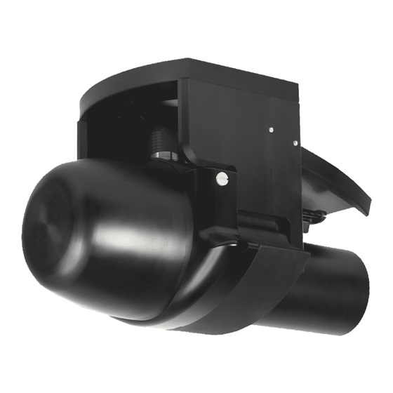
- Page 17 Wet-End Overview WBMS Sonar Head The WBMS sonar is comprised of a cylindrical receiver array and a cylindrical projector array. The receiver housing contains latest FPGA boards where all sonar processing occurs. Data leaving the WBMS wet-end is ready for survey data acquisition via Ethernet protocol.
- Page 18 The topside interface unit is identical to the SIU-I-NAV described earlier. To provide yet another option, the STX, in bathy mode, may be coupled to another NORBIT sonar to form a dual-head system for increased coverage and faster results. However, due to the STX’s higher power requirements a dual-head system compromising of at least one STX will require two topside units.
- Page 19 *Please note that SIU-I model 29024-5 and newer will not have the 6A fuse in the rear. Instead there will be an internal 20A fuse This SIU works with all WBMS Bathy, STX and FLS systems. The iWBMSe and iWBMSc require an 18-pin to 10-pin adaptor.
- Page 20 Fuse Socket** Rear; 12A slow blow * Please note that NORBIT has a split serial option. This option allows for ASCII/Binary output of GNSS/INS information to 3 serial connections. Please contact NORBIT support for more information. **Please note that SIU-I-NAV and SIU-I-Compact-NAV models 29028-5, 29029-3 and newer will not have the 12A fuse in the rear.
- Page 21 For the full pin description, refer to the appendices at the end of the manual. The Aux port can connect to an additional WBMS to operate in a traditional dual head configuration with either sonar projecting down, or one looking forward for obstacle avoidance in challenging environments.
-
Page 22: Mounting Considerations
For any questions about mounting, please contact NORBIT Support. If not using an integrated WBMS, then fixing the IMU on the survey pole reduces the need for well-designed and robust mounting systems that allow the most minimal flexing with respect to the survey platform. - Page 23 Sonar Mounting Location Generally, the WBMS Reference Point should be clear of the lowest part of the hull, at the mounting location. This is to avoid reflections from hull and water surface. A strong hull-reflection will reduce SNR for all beams (simply rotating the wedge in software will not blank out a strong reflection).
-
Page 24: Sensor Mounting
✗ ✓ CAUTION: Electrically Isolate WBMS from Metal Boat ⚠ If using a custom-built WBMS mount that is not provided by NORBIT, please use a non-conductive plate to electrically isolate the sonar. This will help prevent corrosion. 10.4.3 User Manual... - Page 25 Loctite 242 Blue to prevent loosening of sonar during long deployments. The bolt hole pattern shown above is applicable for all integrated WBMS systems. The sonar and IMU cables should never be connected or disconnected underwater. Ensure all connector pins and sockets are clean, dry and shin.
- Page 26 2-3cm. Hull Mount The WBMS can be permanently hull-mounted to a vessel for operations that do not require the system to be portable. The following images are examples of hull-mounted assemblies. When hull- mounting, the sonar pod must be carefully designed to prevent formation of bubbles and to allow water to flow over the SV sensor.
- Page 27 5V, doing so may cause unwanted issues. In addition, the time duration should be 1µ-200ms. For the standalone WBMS, the SIU should receive a PPS TTL input at 3.3V (5V tolerant). The SIU can autodetect negative or positive PPS input and has ±15kV ESD protection, ±60V fault protection.
- Page 28 To connect a GNSS to a stand-alone WBMS, the accompanying timing cable should be used. The cable splits the signal so that both the survey computer and SIU can be connected to the same port from the GNSS. The following are two examples of ways to connect the SIU and PC to the GNSS: 10.4.3 User Manual...
- Page 29 IMU mounting angles. The relevant offsets and misalignments are applied automatically in the WBMS GUI, so the user does not have to input them. The only case where the user must know these values is if a custom installation is used, or if the Applanix firmware is older than 9.03 and all offsets are entered manually in POSView.
-
Page 30: Reference Points
The purple dot indicates the Top Center of Bracket. This is merely a convenient point from which to measure the primary GNSS antenna offset, as the WBMS and IMU reference points are not necessarily physical points that can be directly measured. Refer to section for all relevant offsets and mounting angles for each WBMS configuration. - Page 31 Sonar Offsets & Mounting Angles WBMS Ref. Point Sonar Part No. Mounting WBMS Ref. Point to to Top Center of (* denotes values that Angles Sonar Kit and Bracket PN Name in GUI IMU Ref. Point Bracket may be ignored for...
-
Page 32: System Operation
USB drive. It can also be downloaded free of cost from Microsoft. Microsoft has stopped mainstream support of Windows 7 as of January 13, 2015. Starting with 10.3 NORBIT does not test software for compatibility with Windows 7. -
Page 33: Network Configuration
Connecting INS to Connect. Operation Without GUI (Headless/Passive Mode) Some setup of the NORBIT WBMS, such as AUV/ROV may require use of the system without the NORBIT GUI. NORBIT refers to this as headless mode. When operating in this mode, users can interface with the sonar on a script level, directly giving commands to the sonar without the use of the NORBIT interface. - Page 34 Connect to Sonar Upon launching the GUI, the Connection Dialog is displayed. If a sonar is active and, on the network, a green light is displayed next to it. A red light indicates that the sonar is not online. If a red light is shown, and the sonar is powered on, check the network configuration (see section 4.2).
- Page 35 INS Setup Wizard allows users to configure offsets and GNSS corrections. For users with standalone WBMS systems, or iWBMSc, most settings under INS Tools are greyed out. Users with integrated systems must have Applanix firmware v9.03 or later. To request an upgrade, open POSView and select View >...
- Page 36 (also known as True Heave), or to post-process GNSS data using POSPac. Note that the above group selections are pre-configured and cannot be changed in the NORBIT GUI. All groups required by the acquisition software (HYPACK, QINSy, PDS, EIVA, etc.) are included in the pre-configured selection.
- Page 37 Selecting Plan View or Profile View displays a diagram showing the antenna positions with respect to the WBMS Reference Point. This can be used for a visual check of the system layout/offsets. NOTE: NORBIT GUI and POSView/POSPac Offsets Are Different ⚠...
- Page 38 Center of Rotation Offset The vessel Center of Rotation (CoR) offset should be entered relative to the Measure Point. Note that the center of rotation is more of an area rather than a well-defined point on the vessel, therefore an approximation will suffice. Select Use CoR Offset and enter the measured values under Measure Point to Center of Rotation (CoR).
- Page 39 GNSS Input. Then enter the offset to the auxiliary antenna phase center. It is important to note that this offset must be measured from the WBMS Ref. Point (see section 3.1) to the phase center of the auxiliary antenna. When the auxiliary system is connected, the INS compares its own solution against the quality of the auxiliary solution and automatically selects the best.
- Page 40 To enable RTK corrections via NTRIP, select Ethernet as the RTK/DGNSS Input. Select NTRIP Client and enter the login details. Select Fetch Sources, and then select the source from the dropdown menu. Click Connect. When the NTRIP client shows Bytes Received and Bytes Sent values increasing, a connection is established.
- Page 41 Check that the results are sensible and select Commit to save the results. NORBIT recommends performing a patch test after the heading alignment. 10.4.3 User Manual Contents April 17, 2020 Firmware: 5.2.1...
- Page 42 This can be used to bring the antennas and iWBMS into alignment either by adjusting the mounting angle of the WBMS in the Z axis, or by adjusting the antennas. By using an iterative process of adjustment and calibrations, the user can achieve a high degree of alignment between the antennas and the WBMS.
- Page 43 Version information is displayed at the bottom. It displays all INS related hardware, software and firmware versions. For users requiring an authorization code to upgrade the INS firmware, NORBIT support may ask for a screenshot of this display.
- Page 44 Subscribing to Marinestar Follow the steps below to activate a Marinestar subscription for decimeter-level GNSS corrections, assuming RTK is not available: 1. Select INS Tools > System Status and obtain the OMNSN number: 2. Go to http://www.fugroMarinestar.com/Order_form and request a subscription. In your request, you must supply the OMNSN number from the previous step.
- Page 45 Post-processing the GNSS data allows RTK dropouts to be recovered. TSS1 For standalone (non-integrated) WBMS systems, a TSS1 message can be interfaced from an external motion sensor for roll stabilization. The TSS1 message should be interfaced to the computer via a COM port.
- Page 46 The software and firmware versions are displayed at the top right corner. Check the NORBIT support web pages to verify that you have the latest version.
- Page 47 View Most sonar control features can be found in the View menu. The user may specify Gate Mode, the Upper and Lower Gates, Swath angle and swath pointing Direction. The table below describes each function in detail. Sonar range is a function of the Lower Gate, angular Swath width and swath pointing Direction.
- Page 48 (unlike regular side scan) a correctly positioned side scan can be derived from snippets data. When surveying with a WBMS STX model, if snippets and/or side scan data are required, users are advised to deactivate Scanning in Tx Pulse Settings. If the goal is to classify bottom types, collection of Snippets will be most helpful.
- Page 49 Description Frequency Sets center frequency of transmitted pulse. The WBMS is optimized for a center frequency of 400kHz for standard systems and 200kHz for deep/long range systems. For a given depth, higher frequencies theoretically have higher bottom detection resolution, but also higher signal attenuation, especially in the presence of sediments.
- Page 50 Ping Rate Sets the rate at which acoustic pulses are transmitted. Certain factors such as depth will limit the maximum achievable ping rate. For instance, in deeper water, lower ping rates will be the norm since signal travel time and path length from projector to reflective bottom, and then back to receiver, are longer.
- Page 51 It is prudent for the sonar operator to understand the Advanced settings in the rare event that they need to be changed. If a WBMS STX system is utilized, an additional checkbox appears for activating pitch stabilization. Note that pitch stabilization should not be used when Scanning is selected.
- Page 52 For marine conditions requiring a larger range, other models of the sound speed probe are available; please contact NORBIT for more information. Auto Sound If this option is selected the speed of sound is read from the probe at the sonar head.
- Page 53 Options (Display Display Preferences Preferences, Bottom Point Size – Changes the point Timing and Triggering, size on the wedge. Adjustable from 1-10. Paths) Display Text Size – Changes the text size on the wedge area. Adjustable from 1-12. Roll Rotation – Viewing options to show the roll stabilized wedge.
- Page 54 Connection The WBMS operates in a native data format. To ensure compatibility with other data acquisition and processing software, the system includes a proxy that translates native WBMS data to the well-known s7k data format. The proxy is therefore run from the GUI and is initiated automatically.
- Page 55 USB drives, etc. select Browse and navigate to the correct folder. To play back a recording, double- click the file name. This opens a second display next to the active wedge showing the recorded data. By default, recordings are stored in: C:\Users\<user>\NORBIT\WBMS\ During playback, only bathymetry and water column data will be displayed.
- Page 56 The Info tab contains a record of serial numbers, part numbers, revision numbers, and various system statistics. The Version tab displays the current WBMS GUI version, as well as the current firmware version. Presets Users can save preferred sonar configurations to a file by selecting Save Config. These files can be loaded by selecting Load Config, as and when required.
- Page 57 Upper GUI Status Indicators The first row of indicators (Sonar) shows the streaming status of various data types as it is requested by acquisition software. Data not requested shows a grey indicator. If the SS, SN or WC indicators are red, it indicates that the signal is saturated. Adjust the TVG settings under Backscatter Controls, as described in section Indicator Description...
- Page 58 Users may record bathymetry data with full motion and navigation data (for Applanix integrated systems only) in the native NORBIT format with extension *.wbm. Since NORBIT GUI 10.4 was released, s7k files are generated automatically at the same time as wbm files and include True Heave data.
- Page 59 Successful requests are replied with record 7501 (ACK) while unsuccessful ones return record 7502 (NACK). This is based on RESON’s data format definition (DFD) version 2.43. The following table describes the current s7k records output by the Proxy Server contained in the NORBIT GUI: Record...
- Page 60 Connect the sonar to the Ethernet switch and then the controlling PC to the switch. Configure the network settings on the controlling PC as described in Section 4.2, noting the IP address of this computer. Install the WBMS GUI and configure it as described above. Power on the sonar and launch the WBMS GUI.
-
Page 61: Theory Of Operation
If in manual mode and operating in shallow waters, select FM Short Range mode to maximize ping rate. The NORBIT WBMS has been tested to 175m using 80kHz bandwidth. It is recommended that for most scenarios, users select the Auto option under Tx pulse settings. - Page 62 STX (Steerable Transmitter) Usage The NORBIT STX is a steerable projector system that allows the transmit beam to be directed forward 10° and aft 10°, in a scanning pattern, along the vessel track. This scanning allows the system to ensonify areas that otherwise would not be, such as behind pilings. This functionality aids inspection surveys by giving a more complete picture of the survey area or target.
- Page 63 Survey Calibrations & Checks Before starting a survey (or during longer surveys) it is best practice to regularly check the performance and alignment of the sonar system. The following procedures are vital in maintaining quality control of depth measurements. Patch Test The Patch test resolves small misalignments between the sonar and the navigational system.
- Page 64 Bar checks are typically carried out using the Nadir beams to reduce the influence of ray bending due to sound velocity changes. For best bar check results, NORBIT recommends that the WBMS be set up with the following configuration: •...
- Page 65 At the same time, GNSS measurements are taken from the rover and NORBIT data is recorded. The elevation of the rover shots and the final processed elevation of the soundings is then compared. If all sonar equipment is functioning properly and the offsets have been measured correctly then the final difference should be within 1-2cm and often better.
- Page 66 NORBIT provides a dual head solution that is extremely simple to set up and use. Especially in shallow waters, NORBIT’s dual head solution will yield swath coverage of up to 25 times water depth enabling surveyors to collect data very quickly and efficiently.
- Page 67 GNSS/INS or the last two digits of the sonar serial number; set the subnet mask to 255.255.255.0. GUI: Install the WBMS GUI and, with the SIU powered on, run the GUI to detect and communicate with the sonars. On the Connection Dialog, select the two sonars and select the Primary sonar.
- Page 68 For dual head sonar operation, the transmit frequencies of the two sonars must not overlap. When 2 sonars are selected the NORBIT GUI automatically applies a frequency separation to the sonars. This separation is determined in the following way. When a center frequency is selected that GUI will choose a bandwidth, by default, of 40kHz.
-
Page 69: Optional Enhancements
For additional information, please contact NORBIT. Obstacle Avoidance Forward Looking Sonar (FLS) NORBIT’s FLS is a wide beam angle sonar that can be mounted pointing up and looking forward. This configuration was developed to aid surveyors in obstacle avoidance and marine feature monitoring in especially difficult navigational conditions. - Page 70 Windows command prompt. This command pings or checks the input IP address and tests if a connection is present. This is useful for verifying whether NORBIT is communicating with the PC and indicates whether the problem may be somewhere else down the line.
- Page 71 Sonar Simulator For training and certain troubleshooting scenarios, NORBIT provides a sonar simulator that sends simulated data to the standard GUI. The simulator is currently only for sonar data and does not output simulated navigational data. The simulator can be started via the Connection Dialog.
- Page 72 Can still be the problem if firewall is off. • Possible damages sonar cable • Try grounding the SIU • WBMS GUI does not Obtain the latest installation version from NORBIT support: match description in this subsea_support@NORBIT.com and install. manual or software not performing as described in manual •...
- Page 73 Update video drivers on computer. connect displays no data or crashes connect when open • There is data in NORBIT Ensure that both sets of firewalls (Private and Guest or public GUI and INS GUI, but data networks) are turned off. •...
- Page 74 IMU failures, sonar boot up issues. If you do not see a grounding screw on the SIU, NORBIT advises that you use the BNC connection. To ground the system, find a BNC cable and break off the pin inside the connector. On the other end expose the ground shielding, using the outer braid of wires and crimp a connection to them (see below image).
- Page 75 Data Quality Control Checklist The manual details procedures for optimizing NORBIT sonar performance. However, if some simple steps are skipped or not followed closely users may encounter data degradation. This section provides a brief checklist and options to enhance data quality.
- Page 76 100 and less than 255. The system subnet mask should be 255.255.255.0. Verify Power Supply: If WBMS GUI fails to connect to or detect hardware, first check if the system is powered on. If so, check the power supply voltage with a voltmeter. Also, 10.4.3 User Manual...
- Page 77 Socket Pins: Turn off power and check all cable and SIU sockets for bent pins. NORBIT GUI Recording: For issues visible in the GUI display, send NORBIT Support a small recording that shows an example of the problem. Please enable water column (“View WC”) in the NORBIT GUI and include it in the recorded display.
- Page 78 Inspect Pins: PPS LED is blinking at 1Hz, power off system and very carefully check for bent IMU cable and SIU socket pins. If you find bent pins, contact NORBIT Support for immediate instructions on how to fix them. If possible, please send pictures of the bent pins to NORBIT Support.
- Page 79 Please measure the resistances and send the results to NORBIT Support. Factory Reset: For users of iWBMS(x) with Applanix inertial sensors, and NORBIT GUI 10.2 or later, if errors pertaining to the INS persist, attempt a Factory Reset. Go to INS Tools >...
- Page 80 Therefore, each device in HYPACK requires the same identical offset, that is the offset from Center of Rotation to WBMS Reference Point, assuming the CoR is chosen as the HYPACK reference point. If the optional iLiDAR is installed, this offset must be separately measured and applied.
- Page 81 HYPACK Setup for WBMS, iWBMS, iWBMSh & iWBMSe Step 1. Enable HYSWEEP Survey Check Include under HYSWEEP Survey. This allows devices to be added for multibeam surveys. Step 2. Define Boat Select Boat and give it a name. For more intuitive visualization, add a tracking point, preferably to the sonar reference point (for standard installations).
- Page 82 Step 3. Configure Position and Heading Device In Survey Devices, add the Applanix POS M/V Network device and configure it as shown below. 10.4.3 User Manual Contents April 17, 2020 Firmware: 5.2.1 Page 82 of 142...
- Page 83 Step 4. Configure HYSWEEP Interface Then add, and configure, HYSWEEP Interface, checking only the Depth function under Functions: 10.4.3 User Manual Contents April 17, 2020 Firmware: 5.2.1 Page 83 of 142...
- Page 84 10.4.3 User Manual Contents April 17, 2020 Firmware: 5.2.1 Page 84 of 142...
- Page 85 Step 5. Configure Motion Device In HYSWEEP Survey, add the Applanix POS/MV Network device and configure it as shown below: 10.4.3 User Manual Contents April 17, 2020 Firmware: 5.2.1 Page 85 of 142...
- Page 86 Step 6. Configure Multibeam Device Next, go to HYSWEEP Survey and select NORBIT WBMS as shown below. In WBMS Setup, select Sidescan Recording for recording Sidescan only, or Snippet SS Recording for Snippet- Sidescan, or Snippet Recording for logging Snippets. If Snippet data is requested, users must also select Log Datagrams.
- Page 87 10.4.3 User Manual Contents April 17, 2020 Firmware: 5.2.1 Page 87 of 142...
- Page 88 HYPACK Setup for iWBMSc The procedure for iWBMSc users is the same as described in the previous section, except for the following differences in steps 3 and 5: Step 3. Configure Position and Heading Device In Survey Devices, add the Novatel SPAN-SE device and configure it as shown below. 10.4.3 User Manual Contents April 17, 2020...
- Page 89 Step 5. Configure Motion Device In HYSWEEP Survey, add the Novatel SPAN device and configure it as shown below: 10.4.3 User Manual Contents April 17, 2020 Firmware: 5.2.1 Page 89 of 142...
- Page 90 10.4.3 User Manual Contents April 17, 2020 Firmware: 5.2.1 Page 90 of 142...
- Page 91 Therefore, each system in the QINSy database requires the same identical offset, that is the offset from Center of Rotation to WBMS Reference Point, assuming the CoR is chosen as the QINSy reference point. If the optional iLiDAR is installed, this offset must be separately measured and applied.
- Page 92 Database Setup for WBMS, iWBMS, iWBMSh & iWBMSe QINSy structures all data in a native database format. All data and hardware settings including offsets are saved to a database file. The setup locates all sensors relative to an object, usually the survey vessel.
- Page 93 The WBMS is the first instrument that is added. The system requires a name and type. The name can be user defined, e.g. NORBIT and the system type, chosen from the drop-down menu is Multibeam Echosounder. Under socket settings select the Reson SeaBat 7k (TCP/Network) driver.
- Page 94 Offsets are specified in the Multibeam Echosounder Parameters window. Click on the + sign and create a new node called WBMS. Patch test values (roll, pitch and heading) may be entered if known. Enter 512 under max beams per ping.
- Page 95 After completing the previous step, the user is prompted to configure additional related systems. If side scan data is required, add it now. To set up the NORBIT side scan in QINSy configure the pages as shown below. A port and starboard channel must be added and specify the frequency.
- Page 96 Step 8. Add Gyro Compass System Repeat the previous step to add a new system, but this time add a Gyro Compass: Step 9. Add Position Navigation System Repeat the previous step to add a new system, but this time add a Position Navigation System. The Horizontal and Vertical datum will obviously depend on project specifications.
- Page 97 Step 10. Output Quality Information (Optional) To configure the iWBMS, iWBMSh or iWBMSe (with Applanix) to output quality information, add a Miscellaneous system as per below: Step 11. Add Time Synchronization System A time synchronization system must be added. Use binary group 7 without a PPS box. 10.4.3 User Manual Contents April 17, 2020...
- Page 98 Database Setup for iWBMSc The setup procedure is generally the same for iWBMSc users, but with the following differences in Steps 7-10. Step 7. Add Pitch/Roll/Heave System iWBMSc users must configure the Pitch/Roll/Heave Sensor as follows: Step 8. Add Gyro Compass System iWBMSc users with the NovAtel INS should configure the Gyro as follows: 10.4.3 User Manual Contents...
- Page 99 Task Manager with QINSy closed and the USB dongle removed. Look for sntlkeyssrvr.exe and/or sntlsrtsrvr.exe. Close both from Task Manager and try again. Rates in the observation physics display for the NORBIT are incorrect. This may lead users to think that sonar is not pinging properly. This is not the case.
- Page 100 10.3 PDS Setup for WBMS, iWBMS, iWBMSh & iWBMSe The WBMS GUI Version 10 Hotfix requires that Force Push be enabled in the WBMS GUI Connection settings in order to receive data in PDS. Refer to section 4.6.5 for more information on its functionality.
- Page 101 Setup Project Step 1. Create New Project and Setup Geodesy Create a new project in PDS Control Center via File > New Project. Specify a name for the project, and on the next page select a coordinate system from the geodatabase or define a new coordinate system according to the survey requirements.
- Page 102 WBMS Reference Point. This should be a positive value. If the optional iLiDAR is installed, add its offset to the list. This is the measured offset from WBMS Reference Point to iLiDAR Reference Point. Refer to the iLiDAR manual for more details.
- Page 103 PosMV ethernet 3+102+104[hdg] 192.168.53.100 Zero Offset UDP 5602 PosMV ethernet 3+102+104[vru] 192.168.53.100 Zero Offset UDP 5602 Multibeam NORBIT using RESON 7k protocol (1) 127.0.0.1 Zero Offset [mbs] TCP 7000 10.4.3 User Manual Contents April 17, 2020 Firmware: 5.2.1 Page 103 of 142...
- Page 104 Optional drivers may be added for snippets or side scan data, true heave data, and LiDAR data: Group Driver I/O Port Offset Snippets NORBIT using RESON 7k protocol (1) 127.0.0.1 Zero Offset [snp] TCP 7000 Sidescan Sonar NORBIT using RESON-7k protocol (1) 127.0.0.1...
- Page 105 Step 9. Configure Optional LiDAR Properties If the optional iLiDAR is installed, the orientation base must be set in device properties. This should be set to Down-Across assuming the scanner is installed in the standard configuration with connector aft. Refer to the PDS manual for more details. Step 10.
- Page 106 10.4 EIVA Setup for WBMS, iWBMS, iWBMSh & iWBMSe The WBMS GUI Version 10 Hotfix requires that Force Push be enabled in the WBMS GUI Connection settings in order to receive data in EIVA. Refer to section 4.6.5 for more information on its functionality.
- Page 107 NaviPac Setup NaviPac is required to perform a multibeam survey with EIVA. It is utilized by the helmsman display, and some additional information is shared with the online recording module, NaviScan. The configuration is performed via the NaviPac Configuration utility. Applanix POS MV is the only required device.
- Page 108 NaviScan Setup The next step involves adding sensors to NaviScan under the equipment, add sensor drop down menu. To integrate the Applanix INS with EIVA each function must be brought in separately. Therefore, a separate system must be installed for attitude, heading/gyro, and positioning. Step 3.
- Page 109 Step 5. Add Echosounder To integrate the WBMS, go to Add Sensor and choose Echosounder. Select the Reson SeaBat 7k driver. In the port settings select TCP/IP Port, enable Local, and use port 7000. Step 6. Configure Max Beams Click on Reson SeaBat 7k under multibeam in the project tree. To the right of the project tree, under enter 256 for Max beams per scan.
-
Page 110: Appendix A: Quick Start Guide
Sonar Installation: Depending on vessel being used, make an installation plan. Follow this plan to mount sonar (ideally with NORBIT bracket) on the vessel and align unit to be parallel with the vessel keel with the projector pointing aft. Bolt sonar bracket to pole with minimum of 4 bolts. - Page 111 Acquisition: Setup the acquisition software of choice, e.g. HYPACK, QINSy, etc. Offsets to be with respect to the vessel center of rotation. The driver for the WBMS will be the RESON 7125 or 71xx. Newer software, the driver is called NORBIT.
-
Page 112: Appendix B: Advanced Applanix Setup
The features not included are typically used by a small subset of NORBIT users. If you require a feature that is not found inside the NORBIT GUI you may have to utilize POSView. If an item is not found within this section, please refer to the Applanix user guide. - Page 113 GPS. Under Input & Output Configure COM 3 Input to AUX 1 GPS. POS MV on the WBMS. This allows the POS MV to base its positions off the more accurate position obtained from the auxiliary GPS receiver...
- Page 114 IMU as the vessel reference then the IMU to CoR offset is not needed. To decouple the WBMS from the IMU start by removing the four bolts at the back of the iWBMS bracket. This should be done with the iWBMS resting on a padded surface to reduce the chances of damage.
- Page 115 Ref to Center of Rotation Lever Arm During surveys where RTK or PPK are not/cannot be utilized then the offset from WBMS Reference Point to vessel center of rotation should be entered to the Applanix POS MV. Applying these offset aids, the Applanix in properly computing both real-time heave as well as delayed heave.
-
Page 116: Appendix C: Sonar Hardware Dimensions
Appendix C: Sonar Hardware Dimensions 12004 iWBMS / 12007 iWBMSh – Wet-end Dimensions (PN 24003-ACDB) 10.4.3 User Manual Contents April 17, 2020 Firmware: 5.2.1 Page 116 of 142... - Page 117 12004 iWBMS / 12007 iWBMSh 0.95°Tx Wet-end Dimensions (PN 24003-ABDB) 10.4.3 User Manual Contents April 17, 2020 Firmware: 5.2.1 Page 117 of 142...
- Page 118 12005 iWBMSc / 12006 iWBMSe – Wet-end Dimensions – PN 24005/24018 10.4.3 User Manual Contents April 17, 2020 Firmware: 5.2.1 Page 118 of 142...
- Page 119 12003 WBMS – Wet-end Dimensions (PN 24003-ACDB) 10.4.3 User Manual Contents April 17, 2020 Firmware: 5.2.1 Page 119 of 142...
- Page 120 12003 WBMS with 0.95° Tx – Wet-end Dimensions (PN 24003-ABDB) 10.4.3 User Manual Contents April 17, 2020 Firmware: 5.2.1 Page 120 of 142...
- Page 121 WBMS Sonar Interface Unit (SIU) Dimensions (PN 29024) 10.4.3 User Manual Contents April 17, 2020 Firmware: 5.2.1 Page 121 of 142...
-
Page 122: Appendix D: Cable Pinout Diagrams
Appendix D: Cable Pinout Diagrams WBMS Sonar Interface Unit (SIU) Socket Pin Description (PN 29024) 10.4.3 User Manual Contents April 17, 2020 Firmware: 5.2.1 Page 122 of 142... - Page 123 iWBMS Integrated Sonar Interface Unit (iSIU) Dimensions (PN 29028) 10.4.3 User Manual Contents April 17, 2020 Firmware: 5.2.1 Page 123 of 142...
- Page 124 iWBMS Integrated Sonar Interface Unit Socket Pin Description (PN 29028) 10.4.3 User Manual Contents April 17, 2020 Firmware: 5.2.1 Page 124 of 142...
- Page 125 WBMS Interface Cable Pin Description (PN 33029) 10.4.3 User Manual Contents April 17, 2020 Firmware: 5.2.1 Page 125 of 142...
- Page 126 WBMS Interface Cable Pin Description (PN 33075) 10.4.3 User Manual Contents April 17, 2020 Firmware: 5.2.1 Page 126 of 142...
- Page 127 WBMS Interface Cable Pin Description (PN 33029) 10.4.3 User Manual Contents April 17, 2020 Firmware: 5.2.1 Page 127 of 142...
- Page 128 WBMS Interface Pigtail Deepsea Cable Pin Description (PN 33095-x-Lx-D) 10.4.3 User Manual Contents April 17, 2020 Firmware: 5.2.1 Page 128 of 142...
- Page 129 iWBMS Split Cable Pin Description (PN 33129) 10.4.3 User Manual Contents April 17, 2020 Firmware: 5.2.1 Page 129 of 142...
- Page 130 WBMS Interface Pigtail Angled Pin Description (PN 33205) 10.4.3 User Manual Contents April 17, 2020 Firmware: 5.2.1 Page 130 of 142...
- Page 131 D10. iWBMSc Interface Cable Pin Description (PN 33088) 10.4.3 User Manual Contents April 17, 2020 Firmware: 5.2.1 Page 131 of 142...
- Page 132 D11. WBMS Bulkhead Pinout 10.4.3 User Manual Contents April 17, 2020 Firmware: 5.2.1 Page 132 of 142...
- Page 133 D12. iWBMSe Bulkhead Pinout (PN 33169) 10.4.3 User Manual Contents April 17, 2020 Firmware: 5.2.1 Page 133 of 142...
-
Page 134: Appendix E: Mounting Bracket And Pole Dimensions
Appendix E: Mounting Bracket and Pole Dimensions Decoupled IMU Mounting Bracket (PN 45654) 10.4.3 User Manual Contents April 17, 2020 Firmware: 5.2.1 Page 134 of 142... - Page 135 Dual Head Bracket with iWBMSc / iWBMSe 10.4.3 User Manual Contents April 17, 2020 Firmware: 5.2.1 Page 135 of 142...
- Page 136 Dual Head Bracket with iWBMS / iWBMSh 10.4.3 User Manual Contents April 17, 2020 Firmware: 5.2.1 Page 136 of 142...
- Page 137 NORBIT Carbon Fiber PORTUS Pole 10.4.3 User Manual Contents April 17, 2020 Firmware: 5.2.1 Page 137 of 142...
- Page 138 NORBIT Mini Mount Outline with Laser Stand 10.4.3 User Manual Contents April 17, 2020 Firmware: 5.2.1 Page 138 of 142...
- Page 139 NORBIT Travel Mount 10.4.3 User Manual Contents April 17, 2020 Firmware: 5.2.1 Page 139 of 142...
- Page 140 Notes 10.4.3 User Manual Contents April 17, 2020 Firmware: 5.2.1 Page 140 of 142...
- Page 141 Notes 10.4.3 User Manual Contents April 17, 2020 Firmware: 5.2.1 Page 141 of 142...
- Page 142 Notes 10.4.3 User Manual Contents April 17, 2020 Firmware: 5.2.1 Page 142 of 142...
Need help?
Do you have a question about the WBMS and is the answer not in the manual?
Questions and answers