
Subscribe to Our Youtube Channel
Related Manuals for Fast Flow FF-4D-TM-TA

Summary of Contents for Fast Flow FF-4D-TM-TA
- Page 1 Fast Flow 4” Duc le Iron Twin Agitator Centrifugal Submersible Hydraulic Pump Opera on and Maintenance Manual Revision 5—03/01/2021...
- Page 2 C E N T R I F U G A L S U B M E R S I B L E H Y D R A U L I C P U M P Operation and Maintenance Manual Manual: FF-4D-TM-TA Language: English Revision: 4 Fast Flow Pumps LLC 9700 Highway 63 Moss Point, MS 39562 Phone (228) 475-2468 • Web fastflowpump.com...
-
Page 3: Table Of Contents
TABLE OF CONTENTS Safety Informa on ........................... 4 Descrip on ............................5 Technical Data ........................ 5 Patent Informa on ......................5 Agitator Informa on ....................... 6 Installa on ............................7 Unpacking and Hose Installa on ..................7 Hydraulic Connec ons……………………………………………………………………………………………….8 Hydraulic Power Unit Installa on &... -
Page 4: Safety Informa On
•Read and familiarize yourself with both the FF-4D-TM-TA Manual and the HPU’s manual before a=emp ng to operate this pump. Pump service applica ons are seldom iden cal, please call Fast Flow Pumps at (228) 475-2468 if you have any ques ons about your specific applica on. -
Page 5: Descrip On
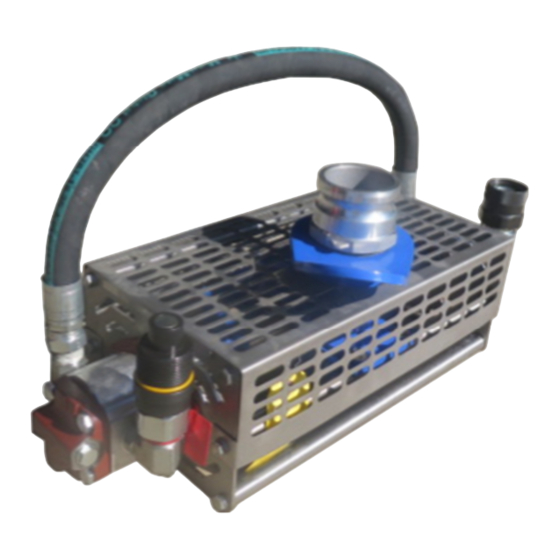
Descrip on This opera on and maintenance manual applies to the Fast Flow Pump model FF 3DTA submersible pump, made up of two major components—the pump head manufactured by Fast Flow Pumps and the Hydraulic Motor mounted on the Pump Head. In order to use this pump system you will also require supply and return hydraulic hose and an hydraulic power unit. -
Page 6: Agitator Informa On
Agitators Safety Precau ons When using any Fast Flow Pump System with a=ached Twin Agitators please observe the following safety precau ons - •Ensure Agitators are installed correctly •Ensure agitators are secure to the drive shaF •Ensure the top debris cage is installed with all agitator pumps •Never use agitator pumps in vicinity of bystanders/personell... -
Page 7: Installa On
•Ensure the hydraulic motor and hose couplings are free of blockage, have not been damaged, and properly match. •Contact Fast Flow Pumps or an approved service provider if any system component appears to be damaged, defec ve, or incomplete. Hose Installa on •Connect the hoses from the power source-connect the return hose first, when turning off... -
Page 8: Hydraulic Connec Ons
Hydraulic Connec ons 1. Clean the ma ng surface of the couplings to avoid contamina ng the circuit. 2. Pull the connec on sleeve of the female coupling forward 3. Align the female and male coupling holding the connec on sleeve and thread together and turning the sleeve. -
Page 9: Hydraulic Power Unit Installa On & Pump Connec On
Fluid Power System | Hydraulic Power Unit (HPU) •Follow any warning s ckers and instruc onal s ckers on the HPU, as well as reading the manual. •Ensure the HPU has a flow of 8-52GPM (30-196LPM) @ 2300-3500 PSI (158-241 Bar) and make sure the system opera ng pressure is set between 1500 PSI to 3000PSI (103-206 Bar.) The normal pressure for most applica ons is 2800 PSI. -
Page 10: Pump Tes Ng Procedures
Dry Run Spin Test The FF-4D-TM-TA is capable of Running Dry for extended periods of me, and it is best prac ce to perform a run dry test before using the pump. To perform this test, first double check that all hydraulic couplings are fully ghtened, then connect the hydraulic system and run the FF-4D-TM-TA pump dry with varying speeds for 1-2 minutes. -
Page 11: Shutdown And Disassembly
Shutdown and Disassembly Shut Down •Slowly shut down the power unit, star ng/stopping fluid flow suddenly can cause damage to the pump and motor seals. In case of Emergency, you can use the emergency shutdown on the hydraulic power unit. Pull handle to close the air inlet to engine. -
Page 12: Exploded View Diagrams
Pump Head Exploded View w/Parts List Fast Flow ⓫ Pump Part Number ⓭ ⓰ FF-4D-TM-TA-SS ❿ ⓯ ❷ ❻ ⓮ ❹ ❼ ❶ ❻ ❽ ❻ ⓱ ⓬ ⓱ ❼ ❺ ⓯ ❻ ❸ ❾ ⓮ Major Pump Parts Description Part No. -
Page 13: Torque Spec Sheet
Torque Spec Sheet/Hardware List ❻ ❿ ❸ ❽ ❶ Hardware List Description Part No. Torque Specs Anti-Seize Loctite Primer 1. 3/8"-16 x 1" (SS) HCS [Hex Head Bolt] HDW113 17 F-lb/23 Nm 2. 3/8" x 7/8" O.D. Flatwasher (SS) HDW065 Not Applicable 3. -
Page 14: Impeller Removal And Replacement
Impeller Replacement Disassembly 1. Disconnect all hoses from the pump head Make certain there is no residual pressure in the hydraulic system 3. Drain off any fluid by inver ng the pump head and clean. 4. Place the pump head on a solid flat surface with adequate working space. 5. -
Page 15: Troubleshoo Ng
Troubleshoo ng Problem Possible Causes Resolu ons Pump will not Turn 1. No hydraulic fluid or pressure. 1. Turn on power unit and test that appropriate flow and pressure is available 2. Bad hydraulic couplers or not with flow gauge and pressure meter. screwed together properly 2. -
Page 16: Warranty
Warranty for Submersible Pumps, Fast Flow Pumps warrants to the original purchaser only that this prod- uct is free from defects in material and workmanship, and agrees to repair or replace, at Fast Flow’s option, any submersible pump part found to be defective within 12 months from the date of purchase. This warran- ty is not transferable.
Need help?
Do you have a question about the FF-4D-TM-TA and is the answer not in the manual?
Questions and answers