
Related Manuals for Furngully GROVE BL-4

Summary of Contents for Furngully GROVE BL-4
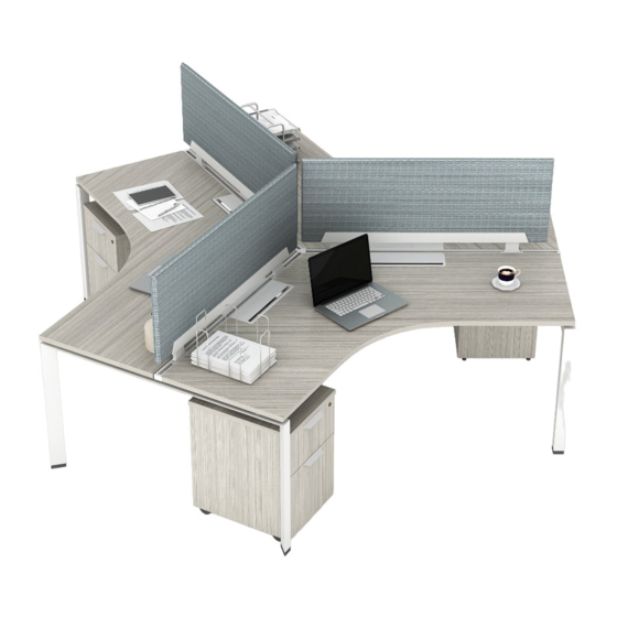
- Page 1 BL–4 GROVE 120 DEGREE WORKSTATION Includes Add-ons A1 | A2 | A5 | A6 | A7 *General Guide | See Master Plan...
- Page 2 EDITION CODE – GROVE 120 Degree Workstation..........1 BL–1 GROVE 120 Degree Pod of 6 ..............11 Add-Ons – GROVE Cable Tray (Leg Mounted) ..........3 – Surface Mounted Dividers ............7 – Laminate Surface-Height End Panel ........15 – Laminate Divider-Height End Panel ......... 17 –...
-
Page 3: Parts List
PARTS LIST PRODUCT CODE BL48 BLPB1 KIT-120 Includes: 120 Degree post leg and triangle box Main Surface... - Page 4 1 | ASSEMBLE 120 DEGREE POST LEG Place the triangle box on the post leg and secure with 4 bolts. Next, attach the corner protector on corner that will be facing toward user when desk is in use. 2 | CONNECT END LEGS, POST LEGS AND BEAMS Insert the beam tabs into the leg brackets.
- Page 5 3 | BOLT DOWN BEAM-TO-LEG LOCK PLATES Place and secure beam lock plates, be sure there is no gap between the beam and the leg or plates will not fit. Insert the screw through the overlapping beam slots and into the black plastic piece.
- Page 6 CABLE TRAY BL–4 | A1 PARTS LIST PRODUCT CODE BCTLM (set of 2) BTEC or BNTEC (set of 2) *if applicable 120 Leg Bracket GROVE POWER IF WORKSTATIONS HAVE POWER, REFER TO BL-8 GUIDE...
- Page 7 1 | ATTACH CABLE TRAY HANGERS AND END CAPS* Align slots on the cable tray and secure with 2 bolts from the bottom. These hangers will mount to a Grove workstation. Insert Beam Grommet Covers. *NOTE: End Caps (BTEC) are optional, follow the same install process with or without end caps.
- Page 8 3 | LEG MOUNT CABLE TRAY Insert tabs of connector bracket into the triangle post leg lots, then use 2 screws to connect the cable tray hanger to bracket. Secure other end of tray directly to Grove end leg using 2 screws. Tighten beam lock.
-
Page 9: Surface Installation
5 | SURFACE INSTALLATION Measure from the inner surface of the leg bracket to the outer edge of the surface. ” Option 1: If you are installing dividers or monitor arms leave a ” space between surfaces, full width should be Option 2: If you are not installing dividers or monitor arms leave a ”... - Page 10 6 | SECURE FIRST SURFACE Position the surface on the desk frame. Align the outer side of the surface flush and parallel with the outer side of the end leg. Insert wood screws into the leg brackets and secure to the underside of the surface.
- Page 11 8 | SECURE SECOND SURFACE Position the surface on the desk frame. Align the outer side of the surface flush and parallel with the outer side of the end leg. Insert wood screws into the leg brackets and secure to the underside of the surface.
- Page 12 10 | SECURE THIRD DIVIDER Position the surface on the desk frame. Align the outer side of the surface flush and parallel with the outer side of the end leg. Insert wood screws into the leg brackets and secure to the underside of the surface.
- Page 13 12 | FINAL SCREW AND TIGHTEN BEAM LOCKS...
- Page 14 PODS OF 6 OR MORE Build an Intermediate leg; this will replace one of the end legs and you will be able to attach another pod. Repeat all steps for a Pod of 3 as needed. Align bracket with leg holes and bolt in place. Connect 4 brackets to the leg.
- Page 15 MEASURE APPROXIMATE LEG SPACING NOTE: The leg spacing will be adjusted as you position the surfaces. 31” 31” 15” 15” 31” 31” 15” 32.5” 32.5” 32.5” 32.5” 15” 31” 31” 15” 15” 31” 31”...
- Page 16 MEASURE APPROXIMATE LEG SPACING Measure from the inner surface of the leg bracket to the outer edge of the surface. ” Option 1: If you are installing dividers or monitor arms leave a ” space between surfaces, full width should be Option 2: If you are not installing dividers or monitor arms leave a ”...
- Page 17 12 | FINAL SCREW AND TIGHTEN BEAM LOCKS...
- Page 18 END PANELS BL–4 | A6 PARTS LIST PRODUCT CODE LEPBL1 GBEPLH## or WABEPSH.(A-D) * Quantities are for one panel...
- Page 19 1 | SECURE BRACKET FOR OUTER PANELS TO END LEGS Attach four brackets to each Grove end leg using the self-tapping screws. The front of the bracket will align flush with outside edge of the leg. Align Flush 2 | ATTACH END PANEL Slide end panels into place and adjust until flush with bracket.
- Page 20 END PANELS BL–4 | A7 PARTS LIST PRODUCT CODE LEPBL1 GBEPSS## or WABEPDH.(A-D) * Quantities are for one panel...
- Page 21 1 | SECURE BRACKET FOR OUTER PANELS TO END LEGS Attach 4 brackets to each Grove end leg using the self-tapping screws. The front of the bracket will align flush with outside edge of the leg. Align Flush 2 | ATTACH END PANEL Slide end panels into place and adjust until flush with bracket.
- Page 22 END PANELS BL–4 | A8 PARTS LIST PRODUCT CODE BEP## or BCEP## * Quantity is for one panel...
- Page 23 1 | SECURE PANELS TO END LEGS Slide the end panel into place and adjust until either flush with outside of leg or slightly recessed. Align Flush Slightly Recessed 2 | ATTACH END PANEL Use 4-6 self-tapping screws to secure panel to each leg.
- Page 24 © 2021 Furngully. All rights reserved.
Need help?
Do you have a question about the GROVE BL-4 and is the answer not in the manual?
Questions and answers