
Related Manuals for GALILEI LIBRA 70

Summary of Contents for GALILEI LIBRA 70
- Page 1 AS/NZS ORIGINAL USERAND MAINTENANCE MANUAL Read carefully and keep for future use LIBRA 70 R290 ORIGINAL INSTRUCTIONS...
- Page 2 THANK YOU! Dear customer, We thank you very much for choosing a product of Galilei Refrigerazione. We wish you a profitable and successful use of this cabinet, meanwhile we kindly ask you to read carefully the content of this manual before its installation and use. The instructions of this manual will provide you all the necessary information to guarantee a safe, effective, and long-lasting use of this equipment.
-
Page 3: For Your Safety
FOR YOUR SAFETY Cabinets working with flammable refrigerant R290 (Propane) End-users and service personnel are required to fully understand and observe the following instructions. Notice: cabinets working with flammable refrigerant are identified by a specific label applied to the side of the base. The Type of refrigerant is also specified in the rating plate, see below picture. Each and every operator, as well as the maintenance personnel, must carefully read und fully understand or have these instructions explained before using this equipment. - Page 4 Warning!! In case the cable or the plug is damaged, ask for a prompt replacement by qualified maintenance personnel. SERVICING, MAINTENANCE AND REFRIGERANT HANDLING R290 is classified as flammable refrigerant of Class A3 according to ANSI/ASHRAE. It is a highly flammable and very easy to ignite.
- Page 5 INDEX General data and features …………………………………………………………………………… General dimensions Unloading and handling of the cabinet Noise level, weights Maximum loading of display decks and shelves Position of water draining outlet and power connection General recommendations ………………………………………………………………………………… Placement of the cabinet Electric connections Preserving the displayed products Cleaning Maintenance...
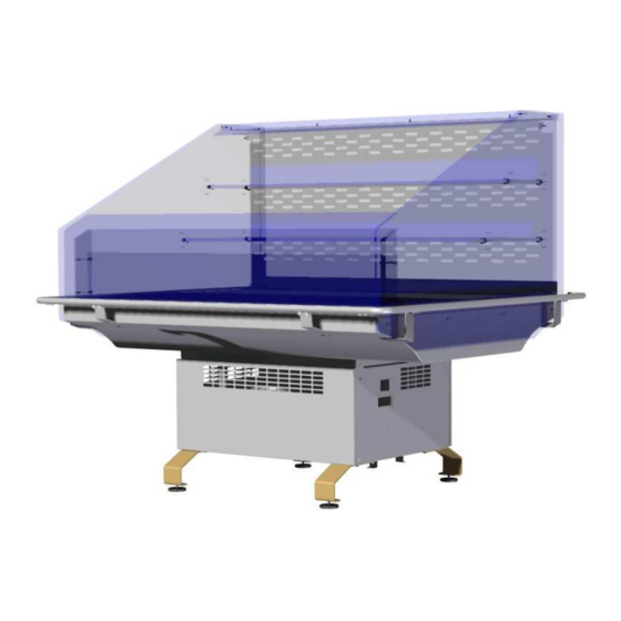
- Page 6 GENERAL DATA AND FEATURES LIBRA 70 semivertical plug-in counter Self-service refrigerated semivertical counter with forced air circulation and built-in condensing unit, suitable for the displaying and merchandising of pre-packed food such as salami and cold meats, cheese, milk and dairy products, delicatessen, fruits and vegetables. Complete with endwalls, display decks in galvanized steel powder-coated in RAL 9005, intermediate shelves in tempered glass adjustable both in height and inclination, front bumper-rail in stainless steel D.
-
Page 7: Noise Level
Unloading and handling of the cabinet in order to be transported, the cabinet is delivered on a Europallet with standard dimensions (120 x 80 cm), and fixed by means of proper fixing plates. Unloading must be carried out by means of a forklift, using the designated handling points for this kind of pallet (along the stringerboards or deckboards, see hatched area on the below pictures). -
Page 8: Maximum Loading
Maximum Loading Top Canopy (width 350mm): 8 kg Upper intermediate Shelf (width 240mm): 12 kg Lower Intermediate Shelf (width 315mm): 16 kg Lower display deck (width 690mm): 80 kg Position of water draining outlet and power connection The cabinet is equipped with a built-in condensing unit and an automatic system for the re-evaporation of the condensing water. -
Page 9: General Recommendations
GENERAL RECOMMENDATIONS It is hardly necessary to pay attention to the following instructions and guidelines, as well as to the pictograms and their meanings. The topics included in this section of the manual have been categorized and grouped according the following criteria: NOTICE: information for a correct and effective use of the equipment. -
Page 10: Electric Connections
Before operating the cabinet, feet/supports must be adjusted so that the unit is stable and perfectly horizontal. Such condition is necessary to guarantee a proper drainage of the defrost water and a running of the equipment without vibrations and noises. In case, adjust the levelling feet (if present) checking at the same time the horizontal alignment with a spirit level, both along the length and the width of the cabinet. - Page 11 Cabinets with remote condensing unit: electric connections and start-up must be carried out exclusively by qualified technical personnel. Cord plugs of external devices/equipment produced by third parties (e.g. slicing machines, weighing machines etc.), and/or power lines for additional sockets (possibly delivered as accessories), will have to be connected to separated power lines installed by qualified personnel, properly sized and protected in respect of the loads to be connected.
- Page 12 The cabinets are equipped with an automatic system for the cyclic defrost of the evaporator. This system is handled by the electronic controller of the control panel. Defrost parameters are pre-set in factory according the necessities and specificities of each unit. In particular cases it may be necessary to manually initiate a defrost cycle, by operating the related function of the electronic controller (make reference to the section of the manual dedicated to the electronic controller).
-
Page 13: Maintenance
Cleaning of the external parts: a frequent cleaning routine helps to keep the cabinets presentable, to preserve it for a long-term use and to convey a sense of cleanliness and hygiene to the customers. It is therefore recommended to clean frequently the external parts of the cabinets, such as glass superstructure, backshelves, cladding panels, aluminium profiles, etc. -
Page 14: Dismantling And Disposal
Safe use of the cabinet This appliance cannot be used by people, including young children, whose physical, sensorial or mental capacities are reduced, or by people who are not properly trained unless they are supervised by a person responsible for their safety. Young children should be supervised to ensure that they do not play with the appliance Unsuitable use of the unit, or part of it, is strictly forbidden. - Page 15 Cod. 80000080c – 17.07.2018...
- Page 16 NAMEPLATE The nameplate is normally placed beside the control panel, or inside the counter in case of multideck or island unit. The plate contains all the necessary information to identify the unit, and the technical specifications for its correct installation and functioning. The cabinet is subject to WEEE European Directive 2002/96/EC (only for plug-in cabinets) RoHS The cabinet is compliant with RoHS European Directive 2002/95/EC (only for plug-in cabinets)
- Page 17 Meaning of the rating plate fields Model name, with length in centimeters and possible additional marks identifying a given version Attention: this information must always be provided when requiring any spare-part Serial number, code and/or configuration number (if present) Attention: this information must always be provided when requiring any spare-part Year of manufacturing Climatic class, indicating the proper environment conditions in which the unit operates correctly.
- Page 18 Pagina lasciata bianca intenzionalmente This page intentionally left blank Diese Seite wurde absichtlich leer gelassen Page laissée volontairement blanche Pàgina dejada blanca expresamente Cod. 80000160a – 22.01.2014...
- Page 19 TECHNICAL SECTION W A R N I N G This section of the manual is intended only for installation technicians and maintenance personnel. Cod. 80000110a – 22.01.2014...
-
Page 20: Installation And Start-Up
INSTALLATION AND START-UP Installation of the front glass The front glass is kept in its mounting position by a longitudinal slot made on the top side of the front facia. Once removed the packaging of the front glass and its protecting film (if present), insert the lower rim of the glass inside the slot gently pressing downwards, until it reaches the bottom of the slot. - Page 21 Removing the perforated backside panel The perforated backside panel, made of transparent polycarbonate (see section “General Data and Features”, part no. 21) can be easily removed for the usual cleaning operations. Caution: before starting any cleaning operation it is MANDATORY to switch-off the cabinet and to disconnect the plug from the electrical outlet.
- Page 22 3) Extraction of the backside panel The backside panel is kept in its mounting position by 2 Plexiglas pins (a) fixed to the internal upper side of both endwalls, and by 2 polyethylene ledges (b) fixed to both side rims of the injected body. In order to extract the backside panel it is necessary to lift it vertically up until its side upper slots are aligned to the Plexiglas pins (upper “release”...
- Page 23 RIPIANI INTERMEDI–ZWISCHENAUSLAGEN ÉTAGÈRE INTERMEDIAIRE – INTERIM SHELVES Mod.: LIBRA 15’ H:385mm H:245mm 8 pcs. Cod. 80001840a – 01.12.2014...
- Page 24 4 + 4 pcs. H:245mm H:385mm Cod. 80001840a – 01.12.2014...
- Page 25 BATTICARRELLO–STOßLEISTE–PARE CHOC–BUMPER RAIL Mod.: LIBRA 20’ 6 pcs. M6x20 8 pcs. Cod. 80001900– 02.12.2014...
- Page 26 sinistro destro links rechts gauche droite left right Cod. 80001900– 02.12.2014...
- Page 27 CANALIZZAZIONE–ZUSAMMENBAU CANALISATION-MULTIPLEXING Mod.: LIBRA / LIBRA 30’ 4mm & 3mm M6 (X8) Cod. 80002790 – 29.04.2015...
- Page 28 Cod. 80002790 – 29.04.2015...
- Page 29 Cod. 80002790 – 29.04.2015...
- Page 30 LIGHTING FOR INTERMEDIATE SHELVES Mod.: ̴ 15’ 4 + 4 Cod.80002950 - 14.2.2017...
- Page 31 LIGHTING FOR INTERMEDIATE SHELVES Cod.80002950 - 14.2.2017...
- Page 32 Pagina lasciata bianca intenzionalmente This page intentionally left blank Diese Seite wurde absichtlich leer gelassen Page laissée volontairement blanche Pàgina dejada blanca expresamente Cod. 80000160a – 22.01.2014...
- Page 33 Pagina lasciata bianca intenzionalmente This page intentionally left blank Diese Seite wurde absichtlich leer gelassen Page laissée volontairement blanche Pàgina dejada blanca expresamente Cod. 80000160a – 22.01.2014...
- Page 34 Pagina lasciata bianca intenzionalmente This page intentionally left blank Diese Seite wurde absichtlich leer gelassen Page laissée volontairement blanche Pàgina dejada blanca expresamente Cod. 80000160a – 22.01.2014...
- Page 35 LIBRA R290 DIXELL XR50CX INDEX Control panel (DIXELL XR50CX) ……………………………………………………………………… Electronic controller, switch-on and switch-off of the unit Normal conditions of operation User-level settings User interface, Set-point temperature Defrostings, Alarm warnings LED Lighting system ……………………………………………………………………… SECTION RESERVED TO INSTALLATION AND MAINTENANCE PERSONNEL Programming of the controller ……………………………….………………………………………...
- Page 36 CONTROL PANEL (DIXELL XR50CX) This cabinet with built-in condensing unit has a control panel equipped with an electronic controller (pos.2) DIXELL mod. XR50CX. This microprocessor-based controller is equipped with a LED display and has been specifically developed for the management of refrigerating units, display cabinets and showcases. The LED display contains 3 digits and a decimal point, for an easy reading of temperatures, parameters and their respective values.
-
Page 37: User Level Settings
product label). For the modification of the set point make reference to the following chapter of this manual. Attention: The cabinet is equipped with a digital thermometer placed inside the display area, (commonly inside the air-intake grill, just behind the front glass). The preserving temperature is exclusively displayed by this thermometer, and not by the display of the electronic controller. - Page 38 User Interface – keypad The keypad consist of 6 buttons, whose multiple functions are described below. ATTENTION: The “On/Off” button is not an isolator switch and, as factory default, it is disabled by a specific parameter (“onF” parameter). It is recommended not to change this factory setting. In case this function must be enabled, ask the service personnel to modify the parameter mentioned above.
- Page 39 Min. Temperature recorded Press and release the DOWN button. The “Lo” message will be displayed followed by the minimum temperature recorded. By pressing the DOWN button again or by waiting 5sec. the normal display will be restored. Max. Temperature recorded Press and release the UP key.
- Page 40 Alarm Recovery Probe alarms P1”, “P2”, “P3” and “P4” start some seconds after the fault in the related probe; they automatically stop some seconds after the probe restarts normal operation. Let the connections to be checked by maintenance personnel before replacing the probe. Temperature alarms “HA”, “LA”...
- Page 41 LED LIGHTING SYSTEM On/Off switching via Dixell XR50CX If installed, the optional LED lighting system is operated via the keyboard of the electronic controller, by pressing the button shown in the below pictures. Please note that the icon on the button can vary according to the different versions of the same controller.
- Page 42 Pagina lasciata bianca intenzionalmente This page intentionally left blank Diese Seite wurde absichtlich leer gelassen Page laissée volontairement blanche Pàgina dejada blanca expresamente Cod. 80000160a – 22.01.2014...
- Page 43 TECHNICAL SECTION W A R N I N G This section of the manual is intended only for installation technicians and maintenance personnel. Cod. 80000110a – 22.01.2014...
- Page 44 PROGRAMMING OF THE CONTROLLER (DIXELL XR50CX) Attention: the access to the programming menus and the modification of the parameters are exclusively reserved to installation and maintenance personnel. A wrong or improper modification of the parameters can lead to malfunctions and/or to a lack of performances. Parameters categories and access to the menus Working parameters are grouped in two different categories: “Pr1”...
-
Page 45: Special Functions
Special Functions Enable / disable the keypad Used to prevent the set point and the other working parameters from being changed when the equipment is located in a place accessible to the public. In order to activate the keyboard lock, keep pressed simultaneously the UP + DOWN buttons for a few seconds, until the blinking message “PoF”... -
Page 46: Parameters Table
PARAMETERS TABLE Attention: the access to the programming menus and the modification of the parameters are exclusively reserved to installation and maintenance personnel. A wrong or improper modification of the parameters can lead to malfunctions and/or to a lack of performances. Cabinet type: Libra R290 Controller:... - Page 47 Sensor for temperature alarm of condenser (np,P1,P2,P3,P4) np÷P4 °C -55÷150 Condenser low temperature alarm °C -55÷150 Condenser high temperature alarm °C 0.1÷25.5 Differential for condenser temp. alarm recovery 0÷254 Condenser temperature alarm delay 0÷23h50’ Delay of cond. temp. alarm at start up n÷y Compressor Off for condenser low temp.
- Page 48 9C@< > == = < C@ A "; " " % & % " " " " #) " " " " ,- " - " " ( " 0/ ! " " + "- , " ,- " " - "...
- Page 52 GALILEI REFRIGERAZIONE S.P.A. – VIA VENETO 29/31 – 35020 DUE CARRARE (PD) – ITALY Tel. +39 049 99 30 650 Fax +39 049 52 11 341 WWW.GALILEISPA.IT...
Need help?
Do you have a question about the LIBRA 70 and is the answer not in the manual?
Questions and answers