Table of Contents
Advertisement
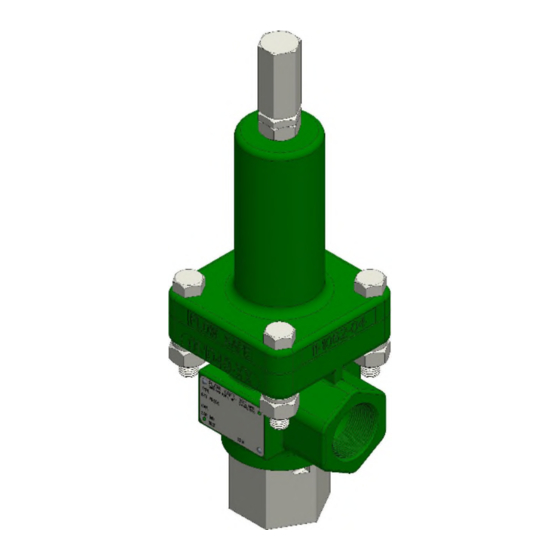
F84L SERIES
SPRING-OPERATED
LIQUID RELIEF VALVE
PLASTIC-SEATED
-2 Orifice (
)
WITH THREADED BONNET
-3, -4, -8, -G, -J Orifices (
)
WITH BOLTED BONNET
INSTALLATION,
OPERATION, & MAINTENANCE MANUAL
Revision:
J
Date of Issue:
Oct. 6, 2021
jwo
GG
Approved by:
Engineering Projects Dir.
Sr. Design Eng.
Advertisement
Table of Contents

Related Manuals for Flowsafe F84L Series


Summary of Contents for Flowsafe F84L Series
- Page 1 F84L SERIES SPRING-OPERATED LIQUID RELIEF VALVE PLASTIC-SEATED -2 Orifice ( WITH THREADED BONNET -3, -4, -8, -G, -J Orifices ( WITH BOLTED BONNET INSTALLATION, OPERATION, & MAINTENANCE MANUAL Revision: Date of Issue: Oct. 6, 2021 Approved by: Engineering Projects Dir.
-
Page 2: Table Of Contents
INSTALLATION, OPERATION, & MAINTENANCE MANUAL TITLE: F84L Series Liquid Relief Valve Rev. J Page 2 of 18 TABLE OF CONTENTS Topic Page General ..................... 3 Description, Operation, Service Envelope, Installation, & Startup Description / Operation ..............4 Service Envelope ................5 Installation .................. -
Page 3: General
This manual is intended to provide users with direction and guidance for the maintenance of FLOW SAFE F84L Series liquid relief valves. This manual indicates the proper method of valve disassembly, soft goods replacement, and valve reassembly. FLOW SAFE provides this manual as a guideline and reference only. -
Page 4: Description, Operation, Service Envelope, Installation, & Startup
CLOSED OPEN The FLOW SAFE F84L Series liquid relief valve is a direct-acting spring-loaded relief valve, suitable for liquid service. The Type F84L is plastic-seated with elastomeric seals. Orifice sizes are available in -2, -3, -4, -8, -G, and -J with set pressures from 30 to 24,277 psig (depending on the orifice size). -
Page 5: Service Envelope
Prior to installation, check that the set pressure on the nameplate is as required, and meets the system requirements. The F84L Series liquid relief valve should be installed in the upright position per the figure on the next page, as close as possible to the pressure source, to minimize pressure losses between the system and the valve. -
Page 6: Startup
F84L SERIES TYPICAL INSTALLATION The F84L Series valves are balanced against superimposed backpressure, so that the set pressure will not change with backpressure. Make sure that the inlet piping/flanges have an opening equal to or greater than the valve's inlet diameter. -
Page 7: Valve Maintenance
INSTALLATION, OPERATION, & MAINTENANCE MANUAL TITLE: F84L Series Liquid Relief Valve Rev. J Page 7 of 18 VALVE MAINTENANCE WARNING: It is extremely dangerous to attempt to disassemble any valve while it remains in service with incoming line pressure. Also, improper assembly of the valve may result in leakage or failure of the valve when returned to service. -
Page 8: Valve Testing And Adjustment
INSTALLATION, OPERATION, & MAINTENANCE MANUAL TITLE: F84L Series Liquid Relief Valve Rev. J Page 8 of 18 Install the seat dry. For bolted-bonnet valves, insert the plastic seat, seat retainer, and retainer screw into the spindle. Apply Loctite or Vibra-tite to retainer screw threads. As screw is tightened, ensure that it meets firm resistance against the locking Heli-Coil in spindle. -
Page 9: Set Pressure Adjustment
INSTALLATION, OPERATION, & MAINTENANCE MANUAL TITLE: F84L Series Liquid Relief Valve Rev. J Page 9 of 18 SETTING / ADJUSTMENT TOLERANCES Set Pressure: Set Pressure Tolerance > 70 psig + 3% of specified set pressure < 70 psig + 2 psi... -
Page 10: Lift Lever Operation
INSTALLATION, OPERATION, & MAINTENANCE MANUAL TITLE: F84L Series Liquid Relief Valve Rev. J Page 10 of 18 LIFT LEVER OPERATION CAUTION: Do not operate a lift lever unless valve inlet pressure is at least 75% of nameplate set pressure. Prepare the system as necessary to handle a discharge from the valve. -
Page 11: Accessories
INSTALLATION, OPERATION, & MAINTENANCE MANUAL TITLE: F84L Series Liquid Relief Valve Rev. J Page 11 of 18 ACCESSORIES Softgoods Kits (SGK’s) NOTE: Provide valve serial number(s) whenever possible when ordering softgoods kits Orifice Std. Kit P/N Lift Lever Kit P/N... -
Page 12: Troubleshooting Guide
INSTALLATION, OPERATION, & MAINTENANCE MANUAL TITLE: F84L Series Liquid Relief Valve Rev. J Page 12 of 18 TROUBLESHOOTING GUIDE: Symptom Possible Cause Remedy The valve leaks around Inadequate bushing torque. Tighten until the bushing bottoms firmly the bushing. on the body. - Page 13 INSTALLATION, OPERATION, & MAINTENANCE MANUAL TITLE: F84L Series Liquid Relief Valve Rev. J Page 13 of 18 TROUBLESHOOTING GUIDE (continued): Symptom Possible Cause Remedy The valve does not Spindle is stuck closed. Disassemble the valve and examine the open. sliding surfaces. If damaged, replace.
-
Page 14: F84L-2 Series "Micro" 2-Pc Body Assembly (Threaded Bonnet)
INSTALLATION, OPERATION, & MAINTENANCE MANUAL TITLE: F84L Series Liquid Relief Valve Rev. J Page 14 of 18 F84L SERIES VALVE ASSEMBLY ILLUSTRATION F84L-2, “Micro” 2-PC (Threaded Bonnet) SPINDLE SEALS (ELASTOMER) PRESSURE RETAINER ADJUSTMENT SCREW (PA) SCREW LOCKING PA SCREW CAP... -
Page 15: F84L-3 / -4 / -8 Series "C" Body Assembly (Bolted Bonnet, Std.)
INSTALLATION, OPERATION, & MAINTENANCE MANUAL TITLE: F84L Series Liquid Relief Valve Rev. J Page 15 of 18 F84L SERIES VALVE ASSEMBLY ILLUSTRATION F84L-3 / -4 / -8, “C” Body (Low Pressure, Bolted Bonnet) PRESSURE ADJUSTMENT (PA) SCREW SPINDLE DRAG SEAL... -
Page 16: F84L-3 / -4 / -8 Series "X" Body Assembly (Bolted Bonnet, Xl)
INSTALLATION, OPERATION, & MAINTENANCE MANUAL TITLE: F84L Series Liquid Relief Valve Rev. J Page 16 of 18 F84L SERIES VALVE ASSEMBLY ILLUSTRATION F84L-3 / -4 / -8, “X” Body (High Pressure XL, Bolted Bonnet) PRESSURE ADJUSTMENT (PA) SCREW SPINDLE DRAG SEAL... -
Page 17: F84L-3 / -4 Series "Z" Body Assembly (Bolted Bonnet, Xxl)
INSTALLATION, OPERATION, & MAINTENANCE MANUAL TITLE: F84L Series Liquid Relief Valve Rev. J Page 17 of 18 F84L SERIES VALVE ASSEMBLY ILLUSTRATION F84L-3 / -4, “Z” Body (Extra High Pressure XXL, Bolted Bonnet) PRESSURE ADJUSTMENT (PA) SCREW PA SCREW CAP... -
Page 18: F84L-G / -J Series "D" "E" "X" Body Assembly (Bolted Bonnet)
INSTALLATION, OPERATION, & MAINTENANCE MANUAL TITLE: F84L Series Liquid Relief Valve Rev. J Page 18 of 18 F84L SERIES VALVE ASSEMBLY ILLUSTRATION F84L-G, “D” or “X” Body (Bolted Bonnet) F84L-J, “E” or “X” Body (Bolted Bonnet) PRESSURE BUSHING ADJUSTMENT HOUSING...
Need help?
Do you have a question about the F84L Series and is the answer not in the manual?
Questions and answers