Advertisement
Quick Links
Advertisement

Related Manuals for E-MAG E-113


Summary of Contents for E-MAG E-113
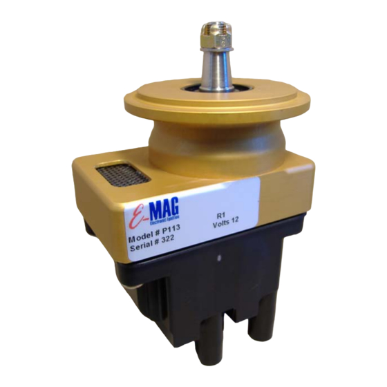
- Page 1 Product Documentation Installation & Operating Guide V L113.6...
- Page 2 Warranty Your E-MAG electronic ignition is warranted for one (1) year from the date of purchase. Any unit returned must first receive a return authorization number prior to shipping (postage paid). E-MAG will repair or replace ignition modules within the warranty period that, in E- MAG’s sole opinion, have not been subjected to abuse or any attempted field repairs.
-
Page 3: Table Of Contents
T able of Contents OVERVIEW ........................................2 DRIVE GEAR ........................................4 CONTROLS ........................................5 SPARK PLUGS & HARNESS ..................................6 INSTALLATION AND TIMING..................................10 OPERATING NOTES...................................... 13 WIRING DIAGRAM ......................................15 CURRENT DRAW......................................16... -
Page 4: Overview
Using This Manual Your E-MAG is designed to make installation as straightforward and as simple as possible. To further assist you, this manual includes a variety of comments and tips. These tips are shown in italics and in dark blue for easier identification and printing. - Page 5 make the LED light up. Firing the ignition without all connections could damage the unit, and void your warranty.
-
Page 6: Drive Gear
NEVER strike the magneto or the gear. Install the drive gear on the E-MAG shaft using the woodruff key, washer(s), castle nut, and cotter key provided. Your kit includes three washers (one thick and two thin). -
Page 7: Controls
MAG in place of a non-starting magneto that was controlled by such a switch, make sure you remove this jumper. You do NOT want a start-up block on any circuit controlling your E-MAG(s). “5” connects to your main 12 volt aircraft buss through a dedicated circuit breaker (not provided) using 18 gauge wire. -
Page 8: Spark Plugs & Harness
This applies to dual E-MAG ignitions as well as split systems (E-MAG in tandem with a magneto or other EI). Note 2: Your E- MAG will generate a tack signal even when it is disabled at the key (or other) p-lead ignition switch, so you won’t loose tack when you switch the... - Page 9 Aircraft Plugs - One advantage of electronic ignition is the ability to fire across a wider spark plug gap (0.030” to 0.035” in the case of E-MAG). Some aircraft plug styles are difficult/impossible to adjust this wide. Plug styles similar to REM37BY have an extended electrode arm that is easier to adjust.
- Page 10 installation. Note: Auto leads should be kept separated when installed. Do NOT bundle them together as is common with shielded aircraft wires, as this can cause them to be inductively coupled. Wire looms can be purchased at auto parts stores, but a simple separator can be fabricated out of tie-wraps and ¼”...
- Page 11 Use the Crimp Tool to trim 1” of shielding from the wire end. Use the largest opening on the tool stripper (position “10”) to GENTLY cut the shield. Make one cut, and then a second cut with the tool rotated 90 degrees to ensure you cut the insulation all the way around the core.
-
Page 12: Installation And Timing
Note 2: These instructions are strictly limited to the installation and handling of “E” model and “P” model E-MAG ignition(s) ONLY. If you are installing dual E-MAGs, pull the breaker AND the coil plug from BOTH ignitions. Reconnect them ONLY as instructed and only for the ignition you are working with. - Page 13 • Low Advance (up to 34 degrees) - WITH jumper. Note 1: E-MAG has NOT tested the myriad of fuel and engine configurations, and cannot prescribe which setting is appropriate for a given situation. In general, builders with high compression engines or those experimenting with auto fuels might want to use the low advance setting.
- Page 14 You can then apply 12 volt power WHILE the p-lead switch is OFF. Without moving the drive gear, position the gasket on the E-MAG flange and install the ignition in the engine accessory case. You will engage the ignition drive gear with a gear inside the accessory case. Don’t worry if you bump the gear and lose your LED light at this point, but try to avoid moving the gear very far off the index (GREEN) position.
-
Page 15: Operating Notes
NOT included with the initial release of series 113 ignitions. Those features are of interest to builders using composite oil sumps. If you are currently using a composite sump, and need these features, contact E-MAG for instructions, and the latest updates before installing your E-MAG system. - Page 16 Powering Down - With all E-MAG models, use your main power switch or breaker(s) to power down the ignitions. The ignition OFF switch (p-lead) only tells the E-MAG to stop generating spark. It does NOT cut power to the ignition. If you leave the craft with your E-MAG(s) powered ON, they will draw down your battery over time.
-
Page 17: Wiring Diagram
Control Alternate Timing Limit Opto Isolator 4. P-Lead (ignition switch to ground stops ignition firing) Aircraft Power (+13.8vdc) through 3(P-MAG) or 5(E-MAG) amp breaker Optional Tack Output* - 12-volt +5 Volts pulse 20 millisecond long - 2 ppr Opto Isolator Outside... -
Page 18: Current Draw
If the buss voltage were to deteriorate (or go away), the curve for the P-MAG would be much different. This chart is provided as an aid to builders for planning their electrical loads under normal operating conditions. E-MAG Ign. Current Map @ 13.8 nominal voltage 0.80 0.70 0.60...
Need help?
Do you have a question about the E-113 and is the answer not in the manual?
Questions and answers