Table of Contents
Advertisement
Advertisement
Table of Contents

Related Manuals for MicroCool BIGHORN Series


Summary of Contents for MicroCool BIGHORN Series
- Page 1 Fog System 2020 Installation & Maintenance Manual Version 3 26 BIGHORN Series MicroCool Web site: www.microcool.com 72216 Northshore St. #103-104 Email: info@microcool.com Thousand Palms, CA 92276, USA Phone: +1-760-322-1111 Fax: +1-760-343-1820 March 26, 2020 Page 1 of 36 BIGHORN_March 2020.docx...
- Page 2 TERMINAL STRIP - POWER ..............................8 ELECTRICAL CONNECTIONS- LOW VOLTAGE ........................8 BIGHORN – VFD BASICS ......................9 MICROCOOL BIGHORN - STARTING THE SYSTEM ..............9 SYSTEM FLUSH ..................................9 WATER & DRAIN VALVES ..............................9 TURN ON POWER ................................9 PUMP IS RUNNING ................................
- Page 3 LOW WATER PRESSURE ..............................10 SYSTEM RUN ..................................10 PRESSURIZING THE SYSTEM ....................10 INSTALL DRAIN VALVES ..............................10 MAN/OFF/AUTO SWITCH ..............................10 PRESSURE REGULATOR ..............................10 DRAIN VALVE SEQUENCE ......................11 SYSTEM ON/OFF ................................11 RAMP DOWN ..................................11 LOW SYSTEM SHOCK .................................
-
Page 4: Table Of Contents
INSTALLATION OF REUSABLE HOSE FITTINGS................15 13.1 WARNING: ..................................16 INSTALLATION OF STAINLESS STEEL LINE FITTINGS ..............16 14.1 INSTALLATION INSTRUCTIONS—TUBE FITTINGS ......................17 14.2 INSTALLATION INSTRUCTIONS-TUBE BENDING ........................ 17 INSTALLATION OF ATOMIZATION LINE ..................18 15.1 METHODS OF SUSPENDING ATOMIZATION LINES ......................18 15.2 USE OF AIRCRAFT CABLE .............................. - Page 5 1. BEFORE STARTING PLEASE READ THIS GUIDE ENTIRELY BEFORE BEGINNING INSTALLATION ALSO, READ SUPPLEMENTAL INFORMATION RELATING TO OPTIONAL CONTROL EQUIPMENT 1.1 CRANKCASE OIL PLUG The pump module crankcase vent has been plugged to prevent accidental oil leakage during shipment. Remove the plug and replace with the supplied vent cap before operating pump unit.
- Page 6 WATER QUALITY 2. WATER QUALITY To obtain the best performance, special consideration should be given to the quality of water used in a MicroCool fog system. MicroCool IS NOT RESPONSIBLE FOR NOZZLE BLOCKAGE DUE TO POOR WATER QUALITY. 2.1 TOTALLY DISSOLVED SOLIDS COUNT Water with total dissolved solids (TDS) counts of greater than 500 parts per million (PPM);...
- Page 7 The outlet hose connection is ¼” Male thread NPT Use care and do not over tighten. 3.4 INLET WATER HOSE MicroCool can supply an inlet hose connection kit for your BIGHORN pump – call your MicroCool specialist and ask for item number IHK0001.
- Page 8 The power supply to the pump module must be hard wired to a correctly rated fuse protected circuit complying with NEC guidelines. NOTE: This pump unit has a frequency inverter. If local electrical code requires a GFCI (Ground Fault Circuit Interrupted), this pump will require a special GFCI unit. Please contact MicroCool for details. 4.4 TERMINAL STRIP - POWER After verifying all of the above, power should be on to the terminal strip located inside the NEMA 3R electrical enclosure mounted on the pump module.
- Page 9 For more details on the VFD drive, the readings and fault status refer to the WEG Drive supplement which is enclosed. 6. MICROCOOL BIGHORN - STARTING THE SYSTEM 6.1 SYSTEM FLUSH The system must be flushed before pressurization. This removes any contaminants such as dirt, brass filings or Teflon tape that have found their way into the system.
- Page 10 6.5 LOW WATER PRESSURE If the inlet water pressure gauge drops below 20 P.S.I. (1.4 BAR) (or out of the green zone) when the pump starts, the pump will go into fault mode and will not start. There must be between 20 PSI (1.4 BAR) and 90 PSI (6.2 BAR) of pressure available to the pump at all times NOTE: should the water pressure drop below the factory preset of 20 psi, the system goes to E06 “FAULT”.
- Page 11 BIGHORN pump and the MicroCool nozzle system. 8.3 LOW SYSTEM SHOCK This BIGHORN system, unique to the MicroCool pump range, is electronically activated to reduce system “shock” and alleviates potential water hammer in the system that can damage the pump and the nozzle system. This procedure is preprogrammed into the Variable Frequency Drive.
- Page 12 • switch change filter • cartridge If the pump still does not run, contact MicroCool for further troubleshooting. 10. SYSTEM MAINTENANCE 10.1 CRANKCASE OIL Initially the Crankcase Oil must be changed after the first 50 hours Crankcase Oil Capacity operation.
- Page 13 Fog evaporation and subsequent humidification or cooling is enhanced by air movement and flow. Continuous cooling requires continuous ventilation (a fresh supply of warm or hot dry air). The proper installation and positioning of the atomization lines across any prevailing airflow can seriously affect performance. Contact a MicroCool Specialist for design recommendations.
- Page 14 11.9 TWISTS & KINKS Avoid twisting and kinking the flexible lines/manifolds while un-spooling and installing. Thermoplastic hose has a "memory" and after a period of time will tend to twist back into the original position. When installing flexible nozzle lines, use of the special tool to re-align nozzles is recommended. Failure to do so may result in twisted lines that may initially look fine but under pressure will move considerably.
-
Page 15: Installation Of Reusable Hose Fittings
13. INSTALLATION OF REUSABLE HOSE FITTINGS Reusable hose fittings are used to make high pressure hose connections. They are used to join manifold hoses to high-pressure pump modules, atomization lines and for numerous other applications. There are various styles of reusable hose fittings, but the method used to fit them to hose is the same. -
Page 16: Warning
Figure 13: National Pipe Thread Figure 14: National Pipe Thread Male (NPTM) Requires PTFE Female (NPTF) Requires PTFE Tape on the Thread Tape on the Male Thread 13.1 WARNING: Improper end fitting installation or lack of lubrication during end fitting installation will cause the inner lining of the hose to be torn, leading to leakage, hose swelling or a blockage. -
Page 17: Installation Instructions-Tube Fittings
(Fig. 3) Figures 1-3. 14.2 INSTALLATION INSTRUCTIONS-TUBE BENDING The stainless steel tubing may be bent to fit around objects with a tubing bender. MicroCool tool part# TKT0012 may be used or you may obtain one locally. March 26, 2020 Page 17 of 36 BIGHORN_March 2020.docx... -
Page 18: Installation Of Atomization Line
15.3 AIRCRAFT CABLE INSTALLATION TECHNIQUE Special tools required: Aircraft Cable cutter & 1/16" Sleeve crimping tool. (Aircraft cable tool kit MicroCool PART# TKT0003) 1. Select the two points from which you require your manifold line or atomization line to span. Points may be existing structures such as roof beams, columns, etc. - Page 19 Figure 5. – Fixing Ratchet Strainer to Aircraft Cable 6. The other end of the Aircraft Cable is now ready to be fixed, however, the cable will have TOP VIEW to be tightened or tensioned to prevent the RATCHET STRAINER atomization line from sagging and to create CRIMP SLEEVE the necessary drainage gradient.
-
Page 20: Special Considerations
Figure 7 – Suspended Aircraft Cable and Atomization Line RATCHET STRAINER/ AIRCRAFT CABLE AIRCRAFT CABLE ATOMIZATION LINE AUTOMATIC DRAIN VALVE POLE/ COLUMN POLE/ COLUMN Figure 8 – Supporting Atomization Line at Mid-Span ROOF STRUCTURE VERTICAL SUPPORTS ATOMIZATION LINE 12. The weight of the atomization lines may cause the Aircraft Cable to sag. To overcome sagging it is necessary to support the atomization line along its length. -
Page 21: Hose Clamp Installation Technique
16. HOSE CLAMP INSTALLATION TECHNIQUE In this fast and simple technique, a hose clamp is used to fix the manifold/atomization line to walls or any surface where there is continuous support. The hose clamp is used at a frequency of approximately 16" (450mm) on-center for flexible line and approximately 36”... -
Page 22: Flexible Manifold Or Flexible Nozzle Line Relief Routing
16.2 FLEXIBLE MANIFOLD OR FLEXIBLE NOZZLE LINE RELIEF ROUTING Figure 9a: RELIEF CURVE 10" RELIEF LOOP 6" MINIMUM RELIEF CURVE Leave extra flex line around corners Loops or Curve at the ends of long flex line runs before corners ***NOTE: When wrapping flexible atomization line around a corner or coming to the end of a long manifold run, leave approx. -
Page 23: Nozzle Angle
Flexible Lines Flexible nozzle lines will require a nozzle orientation tool, MicroCool Part # TKT0001 as shown in Figure 10. The nozzle orientation tool is clamped onto the crimp ferrules on each side of the nozzle and held firmly with one hand. -
Page 24: Atomization Nozzles
With the system running, rub the top of the nozzle with the knurled sides of the nozzle-cleaning tool to remove any heavy build up or work the nozzle cleaning tool (MicroCool Part# TKT0002) 0.007” (0.177mm) wire up inside the nozzle orifice. See Figure 23. Spin the wire around and the blockage will become dislodged. Wear eye protection. - Page 25 Stiff Wire Brush Cleaning Stiff Wire Wheel in Portable Devise MicroCool Nozzle Cleaning Tool MicroCool Part# VTB0001 MicroCool Part# VTB0002 MicroCool Part# TKT0002 March 26, 2020 Page 25 of 36 BIGHORN_March 2020.docx...
-
Page 26: Ul Certificate
CERTIFICATE OF COMPLIANCE 20190307-E352513 Certificate Number E352513-20120418 Report Reference 2019- MARCH-07 Issue Date MICROCOOL Issued to: 72216 Northshore St. Unit 103-104 THOUSAND PALMS CA 92276 INDUSTRIAL CONTROL PANELS This is to certify that representative samples o USL, CNL - Industrial control panels. -
Page 27: Warranty
MicroCool warrants that the goods to be delivered will be of the kind and quality described in the sales order or contract, and will be free of defects in workmanship or material. Should any failure to conform to this warranty appear... -
Page 28: Bighorn Illustrations
22. BIGHORN ILLUSTRATIONS March 26, 2020 Page 28 of 36 BIGHORN_March 2020.docx... -
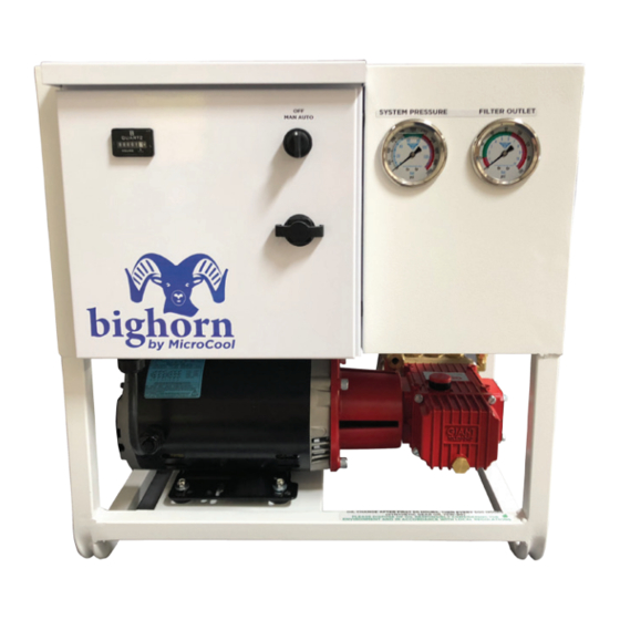
Page 29: Bighorn Front External View
22.1 BIGHORN FRONT EXTERNAL VIEW March 26, 2020 Page 29 of 36 BIGHORN_March 2020.docx... -
Page 30: Bighorn Back External View
22.2 BIGHORN BACK EXTERNAL VIEW March 26, 2020 Page 30 of 36 BIGHORN_March 2020.docx... -
Page 31: Bighorn Right External View
22.3 BIGHORN RIGHT EXTERNAL VIEW March 26, 2020 Page 31 of 36 BIGHORN_March 2020.docx... -
Page 32: Bighorn Left External View
22.4 BIGHORN LEFT EXTERNAL VIEW March 26, 2020 Page 32 of 36 BIGHORN_March 2020.docx... -
Page 33: Bighorn Top External View
22.5 BIGHORN TOP EXTERNAL VIEW March 26, 2020 Page 33 of 36 BIGHORN_March 2020.docx... -
Page 34: Bighorn Top Internal View
22.6 BIGHORN TOP INTERNAL VIEW March 26, 2020 Page 34 of 36 BIGHORN_March 2020.docx... -
Page 35: Bighorn Control Panel View
22.7 BIGHORN CONTROL PANEL VIEW March 26, 2020 Page 35 of 36 BIGHORN_March 2020.docx... -
Page 36: Notes
22.8 NOTES March 26, 2020 Page 36 of 36 BIGHORN_March 2020.docx...
Need help?
Do you have a question about the BIGHORN Series and is the answer not in the manual?
Questions and answers