Advertisement
Quick Links
SKILL 1
In this procedure, you will use the controller's auto-tuning feature to determine the PID values. Then you will
operate the level control loop to observe the response. If the response is not ideal, you will manually tune the PID
values to improve the response.
1. Perform a lockout/tagout.
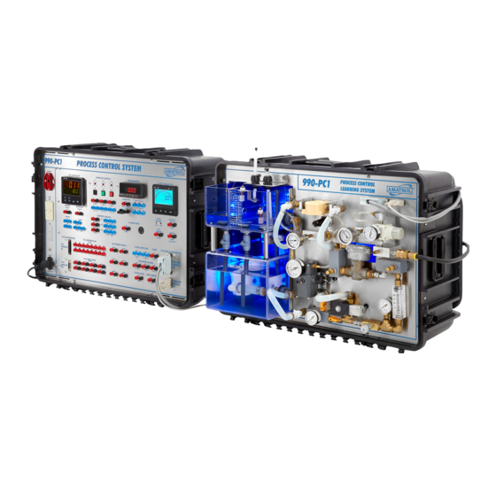
2. Perform the following substeps to set up the 990-PC1, as shown in figure 1-1.
The appearance of the electrical outlet will differ based on the electrical power supplied at your location.
MANUAL
DRAIN VALVE
HV 300 (HV3)
CLOSED
Figure 1-1.
990-PC1 Setup for Closed Loop Level Control
L33354-XA28UEN-E1-S01, REV. A CLOSED-LOOP TUNING
Copyright © 2020 Amatrol, Inc.
TUNE A CONTROL LOOP USING THE AUTO-TUNE METHOD
PROCEDURE OVERVIEW
MANUAL DRAIN VALVE
HV 100C (HV4) CLOSED
HAND VALVE HV 100A (HV2)
AND HV 100B (HV1) OPEN
NOTE
CONNECT THE ANALOG
AND DIGITAL CABLES
15
100 120
80
60
140
160
40
20
180
200
0
kPa
psi
MANUAL FLOW CONTROL
VALVE FV100 (HFV) OPEN
PRESSURE REGULATOR
SET TO 140 kPa (20 psi)
15
100 120
80
60
140
160
40
20
180
200
0
kPa
psi
S01-1
Advertisement

Related Manuals for Amatrol 990-PC1

Summary of Contents for Amatrol 990-PC1
- Page 1 1. Perform a lockout/tagout. 2. Perform the following substeps to set up the 990-PC1, as shown in figure 1-1. NOTE The appearance of the electrical outlet will differ based on the electrical power supplied at your location.
- Page 2 SKILL 1 TUNE A CONTROL LOOP USING THE AUTO-TUNE METHOD A. Connect the air supply line to the 990-PC1. B. Set the pressure regulator to 140 kPa (20 psi). C. Fill the reservoir with water to at least the MIN LEVEL line.
- Page 3 CONTROLLER INPUTS SENSOR Figure 1-3. Wiring Diagram for a Level Sensor Connected to an Electronic Controller Figure 1-4 shows the P&ID for the 990-PC1. The active components and wiring are highlighted. Figure 1-4. 990-PC1 P&ID S01-3 L33354-XA28UEN-E1-S01, REV. A CLOSED-LOOP TUNING...
- Page 4 Once the last parameter is entered for that module, the display will return to CnFP. J. Press the up arrow key until 2-OP (Output Parameters Module) shows. K. With 2-OP displaying, press the P key to enter the output parameters module. S01-4 L33354-XA28UEN-E1-S01, REV. A CLOSED-LOOP TUNING Copyright © 2020 Amatrol, Inc.
- Page 5 Once the last parameter is entered for that module, the display will return to CnFP. P. Press the D key. The display will flash End in the lower display area for a moment, and the controller will return to the main display loop. S01-5 L33354-XA28UEN-E1-S01, REV. A CLOSED-LOOP TUNING Copyright © 2020 Amatrol, Inc.
- Page 6 If the auto-tuning takes way too long, you may stop it by changing the value of tUne from YES to nO. It should finish auto-tuning within four minutes. S01-6 L33354-XA28UEN-E1-S01, REV. A CLOSED-LOOP TUNING Copyright © 2020 Amatrol, Inc.
- Page 7 first occillation. PROPORTIONAL-INTEGRAL-DERIVATIVE CONTROL RESPONSE TIME TIME TIME TIME (seconds) READING (seconds) READING (seconds) READING (seconds) READING Figure 1-8. Table to Record Response S01-7 L33354-XA28UEN-E1-S01, REV. A CLOSED-LOOP TUNING Copyright © 2020 Amatrol, Inc.
- Page 8 70 80 90 100 110 120 130 140 150 160 170 180 190 200 210 220 230 240 250 260 270 280 290 300 TIME (SECONDS) Figure 1-10. Graph of PV (cm) vs. Time S01-8 L33354-XA28UEN-E1-S01, REV. A CLOSED-LOOP TUNING Copyright © 2020 Amatrol, Inc.
- Page 9 70 80 90 100 110 120 130 140 150 160 170 180 190 200 210 220 230 240 250 260 270 280 290 300 TIME (SECONDS) Figure 1-12. Response of the System (PV in cm) S01-9 L33354-XA28UEN-E1-S01, REV. A CLOSED-LOOP TUNING Copyright © 2020 Amatrol, Inc.
- Page 10 Determine if the new values produced a better response than the auto-tuned values. For a process in a plant, you may need several adjustments over a period of days before you reach the ideal PID values. 12. Perform the following substeps to shut down the 990-PC1. A. Place PB1 in the OFF position (out).
Need help?
Do you have a question about the 990-PC1 and is the answer not in the manual?
Questions and answers