Advertisement
Quick Links
SKILL 2
L17401-CL06JEN-E2-S02, REV. C INTRODUCTION TO TROUBLESHOOTING
Copyright © 2019 Amatrol, Inc.
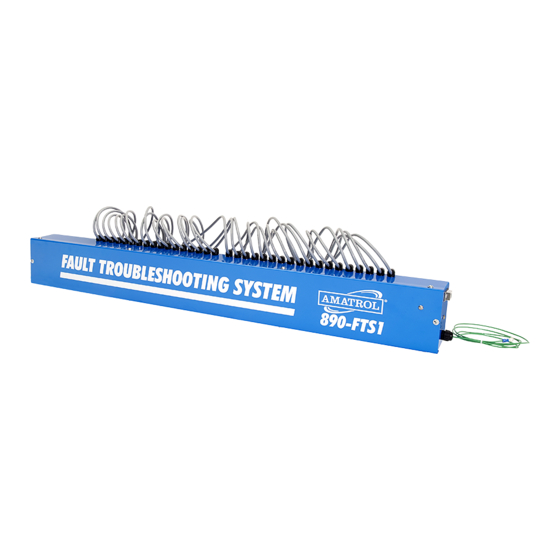
In this procedure, you will test the operation of a pushbutton switch and a
selector switch. To do this, you will insert faults into each component using the
890-FTS1 Troubleshooting System or manual fault plugs.
1. Perform a lockout/tagout on the safety switch of the 85-MT5.
If you are using manual fault insertion, skip to step 3.
2. Perform the following substeps to set up the 890-FTS1 Troubleshooting
System with a power cord.
A. Make sure the troubleshooting system is plugged into a wall outlet.
B. Make sure the troubleshooting system is turned off.
C. Locate the fault terminals at the rear of the Operator Station on the 85-MT5
trainer.
D. Make sure that the fault cables are connected to the 85-MT5 Operator
Station panel in the standard confi guration as shown on the back of the
Operator Station panel and in fi gure 2-1.
OPERATOR STATION FAULT CONNECTION TABLE
Fault Cable Number
TEST A MANUAL SWITCH
Procedure Overview
NOTE
6
7
8
9
10
Connected to Station
Fault Terminal
6
7
8
9
10
S02-1
Advertisement

Related Manuals for Amatrol 890-FTS1

Summary of Contents for Amatrol 890-FTS1
- Page 1 NOTE If you are using manual fault insertion, skip to step 3. 2. Perform the following substeps to set up the 890-FTS1 Troubleshooting System with a power cord. A. Make sure the troubleshooting system is plugged into a wall outlet.
-
Page 2: Operator Station
A. Locate your multimeter and set it to measure resistance. B. Make sure that no leads are connected to the plug-in jacks on the front panel of the Operator Station. If there are, disconnect them. L17401-CL06JEN-E2-S02, REV. C INTRODUCTION TO TROUBLESHOOTING S02-2 Copyright © 2019 Amatrol, Inc. - Page 3 fi rst step of testing the pushbutton. The next step is to test it when the operator is pressed. OPERATOR STATION EARTH Ω Ω PN 17320 Figure 2-2. Pushbutton PB1 N.O. Contacts Out-of-Circuit Test L17401-CL06JEN-E2-S02, REV. C INTRODUCTION TO TROUBLESHOOTING S02-3 Copyright © 2019 Amatrol, Inc.
- Page 4 6 in place of the standard jumper plug. The station fault terminals are located on the back of the station panel. Then, skip to substep J. If not, continue with substep B. L17401-CL06JEN-E2-S02, REV. C INTRODUCTION TO TROUBLESHOOTING S02-4 Copyright © 2019 Amatrol, Inc.
- Page 5 7. Then, go to substep P. If you are using the FaultPro software, continue with substep N. N. Type 7 to insert fault 7 in the Enter Fault fi eld. L17401-CL06JEN-E2-S02, REV. C INTRODUCTION TO TROUBLESHOOTING S02-5 Copyright © 2019 Amatrol, Inc.
- Page 6 This is the opposite result of the N.O. contacts. OPERATOR STATION EARTH Ω Ω PN 17320 Figure 2-4. Pushbutton PB2 N.C. Contacts In-Circuit Test L17401-CL06JEN-E2-S02, REV. C INTRODUCTION TO TROUBLESHOOTING S02-6 Copyright © 2019 Amatrol, Inc.
- Page 7 Fault 8 is now active. This will cause a short in the N.C. contacts of PB2. This condition can occur if the contacts are welded together by high current draw. L17401-CL06JEN-E2-S02, REV. C INTRODUCTION TO TROUBLESHOOTING S02-7 Copyright © 2019 Amatrol, Inc.
- Page 8 PB3 Resistance (pressed) _________________________________ (Ohms) Component Status ___________________________________ (Good/Bad) The contact should be good. This means the resistance should be zero when not pressed and infi nite when pressed. L17401-CL06JEN-E2-S02, REV. C INTRODUCTION TO TROUBLESHOOTING S02-8 Copyright © 2019 Amatrol, Inc.
- Page 9 The faults you have seen so far in this skill involved pushbuttons. These same types of faults can also occur in selector switches. In the remaining steps of this skill, you will test a selector switch. L17401-CL06JEN-E2-S02, REV. C INTRODUCTION TO TROUBLESHOOTING S02-9 Copyright © 2019 Amatrol, Inc.
- Page 10 fi rst step of testing the selector switch. The next step is to test it when the operator is switched. OPERATOR STATION EARTH Ω Ω PN 17320 Figure 2-6. Selector Switch SS1 Contacts Test Method L17401-CL06JEN-E2-S02, REV. C INTRODUCTION TO TROUBLESHOOTING S02-10 Copyright © 2019 Amatrol, Inc.
- Page 11 If the contacts are good, the resistance should be at or near zero. This shows that the contacts are closing when the operator is switched. This selector switch should be good. L17401-CL06JEN-E2-S02, REV. C INTRODUCTION TO TROUBLESHOOTING S02-11 Copyright © 2019 Amatrol, Inc.
- Page 12 D. Remove the lockout/tagout equipment from the safety switch. If this is your last activity for the day, return the equipment to your instructor. If not, continue. L17401-CL06JEN-E2-S02, REV. C INTRODUCTION TO TROUBLESHOOTING S02-12 Copyright © 2019 Amatrol, Inc.
Need help?
Do you have a question about the 890-FTS1 and is the answer not in the manual?
Questions and answers