Table of Contents
Advertisement
Quick Links
Revisions ........................................................................................................................................... 1
1 Specifications ................................................................................................................................. 2
1.1 Performance Parameter ....................................................................................................... 3
1.2 Indicator .............................................................................................................................. 3
1.3 Pinout Description ............................................................................................................... 3
1.4 Product list .......................................................................................................................... 4
2 Modbus-RTU Control .................................................................................................................... 6
2.1 Debugging software description ......................................................................................... 6
2.1.1 Installation and wiring of debugging software ......................................................... 6
2.1.2 Debugging software instructions .............................................................................. 7
2.2 Default Communication Parameters ................................................................................. 10
2.3 Modbus-RTU Description ................................................................................................. 11
2.3.1 RTU Framing ......................................................................................................... 11
2.3.2 Register Mapping ................................................................................................... 11
2.3.3 Register Description ............................................................................................... 12
2.3.3.1 Initialization ................................................................................................ 12
2.3.3.2 Force ............................................................................................................ 13
2.3.3.3 Position ........................................................................................................ 13
2.3.3.4 Speed ........................................................................................................... 14
2.3.3.5 Initialization State ....................................................................................... 15
2.3.3.6 Gripper State ............................................................................................... 15
2.3.3.7 Current Position .......................................................................................... 16
2.3.3.8 Save Parameter ............................................................................................ 16
2.3.3.9 Initialization Direction ................................................................................ 16
2.3.3.10 Slave Address ............................................................................................ 17
2.3.3.11 Baud Rate .................................................................................................. 18
2.3.3.12 Stop Bits .................................................................................................... 18
2.3.3.13 Parity ......................................................................................................... 18
2.3.3.14 I/O Mode Switch ....................................................................................... 19
2.3.3.15 Test I/O Parameters ................................................................................... 20
2.3.3.16 I/O Parameter Configuration ..................................................................... 20
3 I/O Control ................................................................................................................................... 22
Tel/Fax: 0755-82734836
PGC-50 Gripper
Short Manual
Content
www.dh-robotics.com
Advertisement
Table of Contents

Related Manuals for Dh-Robotics PGC-50


Summary of Contents for Dh-Robotics PGC-50
-
Page 1: Table Of Contents
Tel/Fax: 0755-82734836 www.dh-robotics.com PGC-50 Gripper Short Manual Content Revisions ............................1 1 Specifications ..........................2 1.1 Performance Parameter ....................... 3 1.2 Indicator ..........................3 1.3 Pinout Description ....................... 3 1.4 Product list .......................... 4 2 Modbus-RTU Control ........................6 2.1 Debugging software description ..................6 2.1.1 Installation and wiring of debugging software ............ -
Page 2: Revisions
Tel/Fax: 0755-82734836 www.dh-robotics.com Revisions Date Version Revised content First edition, write wiring instructions and 20200801 V1.0 command instructions 20201010 V2.0 Normal update 1. Added functions: Add drop feedback in IO mode, add 04 function code, and further adapt to robots such as AUBO and JICA. -
Page 3: Specifications
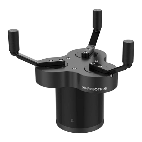
Tel/Fax: 0755-82734836 www.dh-robotics.com 1 Specifications The CGI series is a three-finger cooperative electric gripper, and the number represents the maximum clamping force of a single fingertip. The gripper is equipped with 3 fingertips, which are evenly distributed on a circle. It runs symmetrically during the movement. The main structure of the... -
Page 4: Performance Parameter
Tel/Fax: 0755-82734836 www.dh-robotics.com 1.1 Performance Parameter The specific parameters of CGI-100 gripper are listed in Table 1.1. Table 1.1 CGI-100 specifications CGI-100 performance parameters. Gripping force (per jaw) 30-100N Opening/closing stroke (both sides) Φ40-Φ170mm Opening/Closing time 0.5s/0.5s Weight 1.5kg Position repeatability (both sides) ±... -
Page 5: Product List
Tel/Fax: 0755-82734836 www.dh-robotics.com Figure1.3 Pinout assignment Table 1.3 Pinout assignment The blue Wire The yellow Wire mark mark Wire corresponds to corresponds to Description Explanation number the outgoing the outgoing color color Communication line positive, Green White 485_A T/R+ Communication line negative,... - Page 6 Tel/Fax: 0755-82734836 www.dh-robotics.com Pin 6*10 Pin 3*6 wire 5m extension line module USB to 485 module Note: the content of special customized products will be different. Our gripper standard aviation plug wire is M12 aviation plug. A total of 8 wires are led out, which can be extended by the standard 5m extension wire, as shown in the figure below: Figure 1.4 gripper and extension line...
-
Page 7: Modbus-Rtu Control
Tel/Fax: 0755-82734836 www.dh-robotics.com 2 Modbus-RTU Control 2.1 Debugging software description The debugging software is specially used to control the gripper and set debugging parameters on the computer. Because there is no RS485 interface in the computer, the USB to 485 module is needed to convert the interface to USB interface, which is convenient for the debugging and control of the gripper in the computer. -
Page 8: Debugging Software Instructions
Tel/Fax: 0755-82734836 www.dh-robotics.com create shortcut during installation. Figure 2.2 (a) installation interface 1 Figure 2.2 (b) driver installation interface 2.1.2 Debugging software instructions ‘ Before use, it is necessary to connect the corresponding wiring according to the instructions (see 2.1.1 Installation and wiring of debugging software). - Page 9 Tel/Fax: 0755-82734836 www.dh-robotics.com Figure 2.3 main control interface The specific interface description is as follows: Interface description ·① Initialization and demonstration mode: the gripper needs to be initialized before operation to calibrate the zero point. The demonstration mode is a cyclic program.
- Page 10 Tel/Fax: 0755-82734836 www.dh-robotics.com Figure 2.4 View If there are multiple 485 devices, sometimes the baud rate and ID number of the gripper need to be modified, the parameters can be modified in Modbus RTU parameters Figure 2.5 Modbus RTU parameters You can set and configure the gripper I / O parameters in [I / O parameters].
-
Page 11: Default Communication Parameters
Tel/Fax: 0755-82734836 www.dh-robotics.com Figure 2.6 Modbus RTU parameters The steps of switching IO are as follows: Steps to switch IO mode ·① Open IO mode: open IO mode first. ·② Configure four groups of IO parameters: set the four groups of parameters of gripper, including position, force and speed. -
Page 12: Modbus-Rtu Description
Tel/Fax: 0755-82734836 www.dh-robotics.com 2.3 Modbus-RTU Description 2.3.1 RTU Framing This gripper uses the standard Modbus-RTU protocol. In RTU mode, the first field is the device address. The allowable characters transmitted for all fields are hexadecimal 0 ... 9, A ... F. Networked devices monitor the network bus continuously, including during the silent intervals. -
Page 13: Register Description
Tel/Fax: 0755-82734836 www.dh-robotics.com Gripper’s Closing-force Force 20-100 (%) force currently set (0x0101) Reference position Position Position 0-1000 (‰) currently set (0x0103) Speed Speed Speed 1-100 (%) (0x0104) currently set Initialization Initialization 0:Not initialized;1: state of the Read Only (0x0200) state... -
Page 14: Force
Tel/Fax: 0755-82734836 www.dh-robotics.com direction register). If write 165 (0xA5 hex) to this register will fully initialize the gripper( find the minimal and maximum position). Read: if gripper need to be initialized or have initialized, this register value is 0; and if gripper is in initializing process, this register value is 1. -
Page 15: Speed
Tel/Fax: 0755-82734836 www.dh-robotics.com to the position immediately. The address is 0x0103. The description of this register is shown in Table 2.6. Table 2.6 Position Function Address Description Write Read Reference Reference position Position 0x0103 0-1000 (‰) Position currently set The reference position value range is 0-1000 , the corresponding value is 00 00 –... -
Page 16: Initialization State
Tel/Fax: 0755-82734836 www.dh-robotics.com 2.3.3.5 Initialization State This register is used to store current initialization state of gripper, you can get the initialization state by reading this register. The address is 0x0200. The description of this register is shown in Table 2.8. -
Page 17: Current Position
Tel/Fax: 0755-82734836 www.dh-robotics.com 2.3.3.7 Current Position This register is used to store the actual position of the Gripper. The address is 0x0202. The description of this register is shown in Table 2.10. Table 2.10 Current Position Function Address Description Write... -
Page 18: Slave Address
Tel/Fax: 0755-82734836 www.dh-robotics.com Table 2.12 Baud Rate Function Address Description Write Read Configure 0: Open,1:Close Baud Rate 0x0301 initialization Current setting (default: 0) direction The value of this register is 0 by default. If the register value is 0, when you send the initialization command, the gripper finger will open and find the maximum position. -
Page 19: Baud Rate
Tel/Fax: 0755-82734836 www.dh-robotics.com 2.3.3.11 Baud Rate This register is used to set Baud Rate of gripper. The address is 0x0303. The description of this register is shown in Table 2.14. Table 2.14 Baud Rate Function Address Description Write Read 0-5:115200,57600,... -
Page 20: I/O Mode Switch
Tel/Fax: 0755-82734836 www.dh-robotics.com Table 2.16 Parity Function Address Description Write Read 0: None Parity Configure 1: Odd Parity Parity 0x0305 gripper Modbus Current setting 2: Even Parity Parity (default : 0) The value of this register is 0 by default, corresponding to None Parity. -
Page 21: Test I/O Parameters
Tel/Fax: 0755-82734836 www.dh-robotics.com 2.3.3.15 Test I/O Parameters This register is used to test the I/O Parameters. The address is 0x0400. The description of this register is shown in Table 2.17. Table 2.17 I/O Control Function Address Description Write Read Test I/O... - Page 22 Tel/Fax: 0755-82734836 www.dh-robotics.com ‰ Send: 01 06 04 05 01 2C 98 B6 (Reference position: 300 Return: 01 06 04 05 01 2C 98 B6 Send: 01 06 04 06 00 1E E8 F3 (Force: 30%)) Return: 01 06 04 06 00 1E E8 F3...
-
Page 23: O Control
Tel/Fax: 0755-82734836 www.dh-robotics.com 3 I/O Control The I/O mode is a common control method in industry. The grippers will monitor the pin states of Input 1 and Input 2 (0V and high resistance states). For these two pins, there will be four logic states:00,01,10,11. You can control this gripper through changing the states of Input 1 and Input 2. - Page 24 Tel/Fax: 0755-82734836 www.dh-robotics.com Table 3.1 Input State INPUT 1 INPUT 2 Pin state Perform action I/O state Target position 1,target No wiring No wiring Group 1 force 1,target speed 1 Target position 2,Target No wiring Group 2 Force 2,Target Speed 2...
Need help?
Do you have a question about the PGC-50 and is the answer not in the manual?
Questions and answers