Summary of Contents for CGEO INTERNATIONAL LIMITED CGEO-IPIA
- Page 1 CGEO INTERNATIONAL LIMITED Model CGEO-IPIA /IPIB /IPID MEMS In-place Inclinometer Instruction Manual (REV A) CGEO INTERNATIONAL LIMITED Instruction Manual 1 / 20...
-
Page 2: Table Of Contents
TABLE of CONTENTS INTRODUCTION ............................. 1 IN-PLACE INCLINOMETER COMPOSITION ..................2 CGEO-IPIA /IPIB /IPIDMEMS ............2 MODEL INCLINOMETER TRANSDUCER CGEO-IPIA /IPIB /IPIDMEMS I ............ 3 LACE INCLINOMETER COMPOSITION INSTALLATION .............................. 6 ........................6 REPARING FOR INSTALLATION ................. 6 SE OF CONNECTION PARTS AND INSTALLATION ESSENTIALS ............................ -
Page 3: Introduction
The instrument is installed in standard grooved inclinometer casing. CGEO-IPIA /IPIB /IPID MEMS Horizontal In-Place Inclinometer system is installed in φ 70mm~80mm standard grooved inclinometer casing. Every inclinometer casing can install 12 pieces of instruments ( the number is un-limited if changing the cable layout manner) and connecting through wheel assembly and joint casing, see the figure 1. -
Page 4: In-Place Inclinometer Composition
β as a initial position (that is, β±10°), basing on the obliquity as a standard to measure. The obliquity is provided by customers and customized, marked the installation angle behind the transducer model, like CGEO-IPIA /IPIB /IPID(35°), representing the transducer installation angle is 35 degree. -
Page 5: Cgeo-Ipia /Ipib /Ipid Mems In-Place Inclinometer Composition
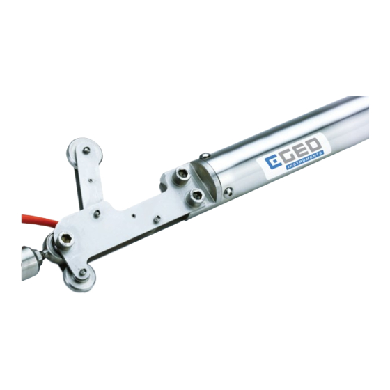
CGEO-IPIA /IPIB /IPID MEMS In-Place inclinometer composition 1)Inclinometer transducer The standard CGEO-IPIA /IPIB /IPID Horizontal In-Place transducer has a threaded hole on the its bottom, mounted a wedged connection parts, which is also possibly not mounted and placed in fitting parts package. - Page 6 58-86mm. The orifice fix component consists of the wedge-shaped coupling used for connection, orifice pendent and suspension link. Every Horizontal In-place inclinometer system is configured one set of orifice fix component. CGEO INTERNATIONAL LIMITED Instruction Manual 4 / 20...
- Page 7 Figure 2-8 one direction and double directions coupling The wedge-shaped coupling consists of connecting threaded rod, wedge-shaped expansion tube, locknut, plain cushion and extended connecting threaded rod. A qualified wedge-shaped coupling can bear not less than 500kg weight CGEO INTERNATIONAL LIMITED Instruction Manual 5 / 20...
-
Page 8: Installation
They have the diameter 60mm, 70mm, 80mm and other specifications, the CGEO-IPIA /IPIB /IPID model is best suit to install inside φ70mm and 80mm inclinometer casing which has the vertical pair of grooves. The installation of the Horizontal In-Place Inclinometer requires only one of pairs of grooves plane locates in vertical direction. - Page 9 Transducer connecting hole or wheel assembly Tube BSIL-C12 Figure 3-2 connection of the connecting tubing and transducer As to the double end joint connection, first connect expansion end and then thread end, see the figure below CGEO INTERNATIONAL LIMITED Instruction Manual 7 / 20...
-
Page 10: Installation Steps
When completing the connection of the two neighboring wheel assemblies, you should measure the central distance between two wheels and record the length L, shown as in the figure below, the distance L will be a important parameter to this position inclinometer calculation. CGEO INTERNATIONAL LIMITED Instruction Manual 8 / 20... - Page 11 L and other relative data. Cable Figure 4-2 CGEO-IPIA /IPIB /IPID whole structure diagram of horizontal in- place inclinometer Cable route: all instrument cable should be parallel routed, more than two cables should wrapped onto the connecting tube, prevent from crossing and avoid occupying too much space.
-
Page 12: Backfill Methods And Recommendations
The backfill instruction is only the case of rockfill, the installation of other fill materials can refer to this method. The backfill materials should be same as the site materials, for example, the CGEO INTERNATIONAL LIMITED Instruction Manual 10 / 20... -
Page 13: Taking Readings
4.1 Function definition of the cable cores of transducer CGEO-IPIA /IPIB /IPID In-Place inclinometer uses an 8 core cable, the 8 core cable consists of 4 twisted pair and another shield wire, the 8 core wire definition as the following:... -
Page 14: Preliminary Test
B =0.124449683838 coefficient 0.0002870555690215 ---current readings -initial readings L-distance between two inclinometers (mm) Note: readout display is half of output voltage of transducer ----Blank below---- Figure 4-6 sample calibration sheet of in-place inclinometer CGEO INTERNATIONAL LIMITED Instruction Manual 12 / 20... - Page 15 Where; LnR Natural Log of Thermistor Resistance A 1.4051 10 (coefficients calculated over the 50 to +150 C. span) B 2.369 10 C 1.019 10 CGEO INTERNATIONAL LIMITED Instruction Manual 13 / 20...
-
Page 16: Insulation Test
θ A′ Figure 5-1 vertical displacement transition principle If multi-instruments in series, the accumulation displacement of these instruments will get the vertical deformation curve of the whole profile. Initial position θ Lsinθ CGEO INTERNATIONAL LIMITED Instruction Manual 14 / 20... -
Page 17: Cgeo-Ipia /Ipib /Ipid Settlement Calculation
(mm); R1-current readings (unit, V) R2-Initial readings (unit, V) The reading range is ±12° when calibrating CGEO-IPIA /IPIB /IPID in the factory, its measurement range can reach±15° when using, the corresponding transducer output is ±12° @ ±4V. CGEO INTERNATIONAL LIMITED... -
Page 18: Temperature Compensation
The thermistor gives a varying resistance output as the temperature changes. The temperature property of CGEO-IPIA /IPIB /IPID is that the signal output will decrease 0.0005Vevery 1℃ rising (the variation in CGEO-PR-MEMS is 0.00025V), then the temperature corrected readings are: RT =R+0.0005 (T1-T0) - Page 19 Symptom: Thermistor resistance is too low. Is there a short? Check all connections, terminals and plugs. ] Water may have penetrated the interior of the tilt sensor. There is no remedial action. CGEO INTERNATIONAL LIMITED Instruction Manual 17 / 20...
-
Page 20: Appendix A - Thermistor Temperature Derivation
21.89K 3000 624.7 176.4 62.5 20.70K 2872 603.3 171.4 61.1 19.58K 2750 582.6 166.7 59.6 18.52K 2633 562.8 162.0 58.3 17.53K 2523 543.7 157.6 56.8 55.6 Table B-1 Thermistor Resistance versus Temperature CGEO INTERNATIONAL LIMITED Instruction Manual 18 / 20...


Need help?
Do you have a question about the CGEO-IPIA and is the answer not in the manual?
Questions and answers