
Related Manuals for CGEO INTERNATIONAL LIMITED CGEO-CR


Summary of Contents for CGEO INTERNATIONAL LIMITED CGEO-CR
- Page 1 CGEO INTERNATIONAL LIMITED Model CGEO-CR Vibrating Wire Crackmeter Installation Manual...
-
Page 2: Table Of Contents
TABLE of CONTENTS 1. INTRODUCTION ....................3 2. INSTALLATION ....................3 2.1. Preliminary Tests ..................3 2.2. Crackmeter Installation ................4 2.2.1. Installation using Weldable Fixtures..........4 2.2.2. Installation using Groutable Anchors .......... 5 2.2.3. Installation using Machine Bolt Expansion Anchors ....6 2.3. -
Page 3: Introduction
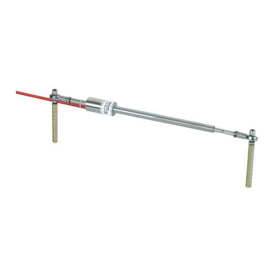
1. INTRODUCTION Model CGEO-CR Vibrating Wire Crackmeters are designed to measure movement across joints such as the construction joints in buildings, bridges, pipelines, dams, etc.;coordinating with other different accessories, and also tension cracks in soils and joints in rock and concrete. The gauge is often adopted surface-mounting manner. -
Page 4: Crackmeter Installation
Table B-1), and between any conductor and the shield should exceed 2 megohms. 2.2. Crackmeter Installation CGEO-CR Model Surface Crackmeter can adopt welding fixture and anchoring manners. You can first weld anchor rod directly on steel member, and then install transducer on anchor rod through the bolts of elbow joint. -
Page 5: Installation Using Groutable Anchors
Figure 4 - Installation using Weldable Fixtures Installation instructions; 1. Determine proper setting distance using figures in Table 1 or the readings on the calibration sheet. Prepare the surface (grinding, sanding, etc.) of the steel around the area of each weldable fixture. -
Page 6: Installation Using Machine Bolt Expansion Anchors
Installation instructions; 1. Determine proper setting distance using figures from Table 1 or the readings on the calibration sheet. Using a hammer drill or other suitable equipment, drill two ½" holes approximately 3" deep at the proper locations. Shorter holes may be drilled if the anchors are cut down accordingly. -
Page 7: Cable Installation
2.3. Cable Installation The cable should be routed in such a way so as to minimize the possibility of damage due to moving equipment, debris or other causes. Cables may be spliced to lengthen them, without affecting gage readings. Always waterproof the splice completely, preferably using an epoxy based splice kit such the dedicated cable heat shrinkable connector kit. -
Page 8: Taking Readings
Figure 7 - Lightning Protection Scheme 3. TAKING READINGS The following three sections describe how to take readings using one of readouts available from CGEO. 3.1. Operation of the CGEO-PR-VW Readout Box CGEO-PR-VW can be used for Surface Crackmeter measurement. Connect the Readout using the flying leads or in the case of a terminal station, with a connector. -
Page 9: Data Reduction
When the environment temperature changes big( over 10 it needs temperature correction and it is performed according to calculation formula supplied in the factory calibration sheet. Please see table 8 and next chapter. VIBRATING WIRE INSTRUMENT CALIBRATION CERTIFICATE : Serial Number 081802 Model:CGEO-CR-50T... -
Page 10: Temperature Correction
Figure 8 - Typical Crackmeter Calibration Sheet 4.2. Temperature Correction The Model CGEO-CR Vibrating Wire Crackmeters have a very small coefficient of thermal expansion so in many cases correction is not necessary. However, if maximum accuracy is desired or the temperature changes are extreme (>10° C) corrections may be applied. The temperature coefficient of the mass or member to which the Crackmeter is attached should also be taken into account. -
Page 11: Environmental Factors
Equation 3 - Thermally Corrected Deformation Calculation Where; is the current reading. is the initial reading. G is the calibration factor. is the current temperature. is the initial temperature. K is the thermal coefficient (see calibration sheet). Consider the following example using a Model J2-25 mm Crackmeter; = 4773 digits = 4589 digits = 20.3°... - Page 12 Is the transducer shaft positioned outside the specified range (either extension or retraction) of the instrument? Note that when the transducer shaft is fully retracted with the alignment pin inside the alignment slot (Figure 1) the readings will likely be unstable because the vibrating wire is now under-tensioned.
-
Page 13: Appendix A - Thermistor Temperature Derivation
APPENDIX A - THERMISTOR TEMPERATURE DERIVATION Thermistor Type: YSI 44005, Dale #1C3001-B3, Alpha #13A3001-B3 Resistance to Temperature Equation: Equation B-1 Convert Thermistor Resistance to Temperature T Temperature in C. Where: LnR Natural Log of Thermistor Resistance A 1.4051 10 (coefficients calculated over the 50 to +150...
Need help?
Do you have a question about the CGEO-CR and is the answer not in the manual?
Questions and answers