aero-stream AS500-1 Installation & Operator’s Manual
Hide thumbs
Also See for AS500-1:
- Installation and operator's manual (38 pages) ,
- Installation and operator's manual (38 pages)
Table of Contents
Advertisement
Quick Links
AS500-1, AS650-1, AS750-1,
Installation/Service Contact:
Name: _________________________
Phone: _________________________
E-Mail: _________________________
Installation & Operator
Guide For Models:
AS1000-1, AS1500-1
Record Product Serial Number here: ___________________
SAVE THIS MANUAL FOR
WARRANTY PURPOSES!
(1) Manual is to be given to
the homeowner prior to
installation.
For additional assistance
please contact us at:
Technical Support
(Toll Free) 877-254-7093
info@aero-stream.com
OR
Advertisement
Table of Contents

Related Manuals for aero-stream AS500-1


Summary of Contents for aero-stream AS500-1
- Page 1 WARRANTY PURPOSES! (1) Manual is to be given to the homeowner prior to installation. Installation & Operator Guide For Models: AS500-1, AS650-1, AS750-1, AS1000-1, AS1500-1 Record Product Serial Number here: ___________________ For additional assistance please contact us at: Technical Support...
-
Page 2: Table Of Contents
Support ..........................3 Permits ..........................3 Read and Keep This Manual ................... 3 Unpack and Inspect Parts ....................3 Overview of AS500-1, AS650-1, AS750-1, AS1000-1, AS1500-1 System and Terminology ......................... 5 System Operation ....................... 5 Before Installation ......................19 Installation Process-Bio Brushes ................19 Installation Process-Diffusers, Air Line and Compressor Housing .... -
Page 3: Support
(Toll Free) 877-254-7093 or info@aero-stream.com Permits This product shall be installed by an authorized Aero-Stream reseller. Prior to the installation of the product, the installer must obtain any and all required state and local permits. The installer must strictly comply with all pertinent state and local requirements. - Page 4 Quantity of items and appearance may differ from items received. Figure 1, Kit Contents © Copyright Aero-Stream, LLC 2003-2019 102821 Rev. D...
-
Page 5: Overview Of As500-1, As650-1, As750-1, As1000-1, As1500-1 System And Terminology
The effluent filter (if required by local or state codes) in the outlet baffle prevents large objects from entering and clogging the outlet pipe. The AS500-1, AS650-1, AS750-1, AS1000-1, AS1500-1 systems are designed to treat residential strength wastewater. This includes human waste and moderate amounts of typical household cleaning products. - Page 6 Contact the authorized service provider to correct the issue. Have the model name and serial number, as found on the bottom plate of the enclosure unit, available when contacting the authorized provider. © Copyright Aero-Stream, LLC 2003-2019 102821 Rev. D...
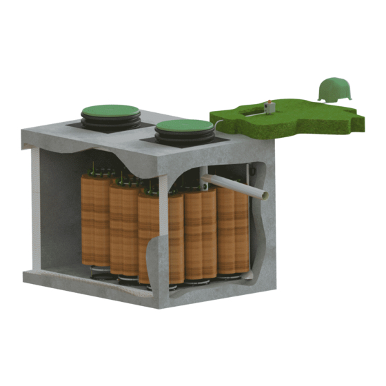
- Page 7 Figure 2A, Picture of the AS500-1 System © Copyright Aero-Stream, LLC 2003-2019 102821 Rev. D...
- Page 8 Figure 3B, Picture of the AS500-1 System © Copyright Aero-Stream, LLC 2003-2019 102821 Rev. D...
- Page 9 Figure 4A, Picture of the AS650-1 System © Copyright Aero-Stream, LLC 2003-2019 102821 Rev. D...
- Page 10 Figure 3B, Picture of the AS650-1 System © Copyright Aero-Stream, LLC 2003-2019 102821 Rev. D...
- Page 11 Figure 4A, Picture of the AS750-1 System © Copyright Aero-Stream, LLC 2003-2019 102821 Rev. D...
- Page 12 Figure 4B, Picture of the AS750-1 System © Copyright Aero-Stream, LLC 2003-2019 102821 Rev. D...
- Page 13 Figure 5A, Picture of the AS1000-1 System © Copyright Aero-Stream, LLC 2003-2019 102821 Rev. D...
- Page 14 Figure 5B, Picture of the AS1000-1 System © Copyright Aero-Stream, LLC 2003-2019 102821 Rev. D...
- Page 15 Figure 6A, Picture of the AS1500-1 System © Copyright Aero-Stream, LLC 2003-2019 102821 Rev. D...
- Page 16 Figure 6B, Picture of the AS1500-1 System © Copyright Aero-Stream, LLC 2003-2019 102821 Rev. D...
- Page 17 Figure 6C, Picture of the AS1500-1 System © Copyright Aero-Stream, LLC 2003-2019 102821 Rev. D...
- Page 18 Figure 5, End of the Plug or see the troubleshooting section below. Figure 6, Overview of the Alarm Figure 7, Electrical Connections © Copyright Aero-Stream, LLC 2003-2019 102821 Rev. D...
-
Page 19: Before Installation
Install a state approved water-tight tank meeting the criteria listed in Table 2, System Requirements on page 55 using industry best practices. Install the Aero-Stream riser assembly per the riser instruction sheet. In an existing system meeting the criteria listed in Table 2, System Requirements on page 55, have the tank pumped prior to installation by a licensed contractor. - Page 20 Figure 18. and Figure 19 Bio-Brush Clusters not shown in Figure 10 through Figure 14 for clarity. Do not remove black ballast rings from clusters. Figure 10, AS500-1 Cluster Arrangement © Copyright Aero-Stream, LLC 2003-2019 102821 Rev. D...
- Page 21 Figure 11, AS650-1 Cluster Arrangement Figure 12, AS750-1 Cluster Arrangement © Copyright Aero-Stream, LLC 2003-2019 102821 Rev. D...
- Page 22 Figure 13, AS1000-1 Cluster Arrangement © Copyright Aero-Stream, LLC 2003-2019 102821 Rev. D...
- Page 23 Figure 14, AS1500-1 Cluster Arrangement © Copyright Aero-Stream, LLC 2003-2019 102821 Rev. D...
- Page 24 Figure 15, Bio-Brush Clusters Connection 1 – 2 Figure 16, Bio-Brush Clusters Connection 2 – 3 Repeat Cluster Connection for Subsequent Rows as Required Figure 17, Bio-Brush Clusters Connections © Copyright Aero-Stream, LLC 2003-2019 102821 Rev. D...
- Page 25 See Figure 20, Cut Packaging Wrap, grasp the float and raise vertically with a slight twisting motion to uncoil the cluster. See Figure 21, Uncoil the Cluster. Figure 20, Cut Packaging Wrap © Copyright Aero-Stream, LLC 2003-2019 102821 Rev. D...
- Page 26 Bio-Brush. See Figure 23, Remove Poly Wrap. Discard the poly sleeve. Repeat this for each Bio- Brush. After unpacking, the Bio-Brush should look like Figure 24, Unpacked Bio Brush © Copyright Aero-Stream, LLC 2003-2019 102821 Rev. D...
- Page 27 12. Stack each cluster of Bio-Brush upon itself with a twisting motion, Figure 25, Stack Bio Brush, similar to how it was before removing the stretch film. Brush will stack as shown in Figure 26, Finish Stack of Bio Brush. © Copyright Aero-Stream, LLC 2003-2019 102821 Rev. D...
- Page 28 NOTE: The installation photos show both blue/white floats and doughnut type floats. The contents of the kit may contain either type of float but the installation steps remain the same for both types of floats. © Copyright Aero-Stream, LLC 2003-2019 102821 Rev. D...
- Page 29 Figure 27, Blue Side of Float Figure 28, Float at Bottom © Copyright Aero-Stream, LLC 2003-2019 102821 Rev. D...
- Page 30 Figure 29, Float in Middle Figure 30, Float at Top © Copyright Aero-Stream, LLC 2003-2019 102821 Rev. D...
- Page 31 Feed the entire gas deflector through the quadrant opening Figure 32, Figure 32, Gas Deflector Insertion Raise the float ring vertically until the Bio-Brushes are fully extended. See Figure 33 through Figure 35. © Copyright Aero-Stream, LLC 2003-2019 102821 Rev. D...
- Page 32 Feed yellow rope through access port of tank and tie rope to screw. See Figure 9, Mounting Screw Location Detail. Figure 33, Brush Installation-1 Figure 34, Brush Installation-2 © Copyright Aero-Stream, LLC 2003-2019 102821 Rev. D...
- Page 33 Brushes. Upon completion, each rope should be tied to a screw, see Figure 37, Secure Brush Ropes. All of the blue ends of the floats shall be aligned towards the outlet side of the tank. Figure 36, Vertical Brushes © Copyright Aero-Stream, LLC 2003-2019 102821 Rev. D...
-
Page 34: Installation Process-Diffusers, Air Line And Compressor Housing
As required, drill a 5/8-inch [16mm] hole through the riser. (See Figure 38, Air Line Exit and Figure 39, Drill Hole in Riser Side Wall. Figure 38, Air Line Exit © Copyright Aero-Stream, LLC 2003-2019 102821 Rev. D... - Page 35 Figure 39, Drill Hole in Riser Side Wall © Copyright Aero-Stream, LLC 2003-2019 102821 Rev. D...
- Page 36 Insert screw and tighten. Step D: Slide air line retainer towards the top of the float tube. Air line retainer should be approximately one-(1) inch [25 mm] below the top of the float tube. © Copyright Aero-Stream, LLC 2003-2019 102821 Rev. D...
- Page 37 (see Figure 41 through Figure 43 below). Figure 41, Diffuser Quadrant Identification Figure 42, Diffuser Insertion © Copyright Aero-Stream, LLC 2003-2019 102821 Rev. D...
- Page 38 No adapter should be used with this product. This product has an automatically reset thermal limiter, which shuts off the entire product when an elevated temperature condition exists. When the product cools, it will automatically restart. © Copyright Aero-Stream, LLC 2003-2019 102821 Rev. D...
- Page 39 Place the Housing on the ground next to the nearest power outlet. The housing can be up to 110-feet from the tank. This will require a 25 – foot, 50-foot or 100-foot air line extension kit. Call Aero-Stream® to purchase. The Housing must always be resting on its base in a horizontal position.
- Page 40 Diffuser is empty. No damage will be done to the system or product. If the tank was pumped, it will take five-(5) to seven-(7) fays for a family of four-(4) to fill a 1,000 gallon tank. © Copyright Aero-Stream, LLC 2003-2019 102821 Rev. D...
-
Page 41: Install Aero-Alert™ Alarm
Install Aero-Alert™ Alarm ® 1. Install the air line/tee fitting in the output air line of the Aero-Stream unit. Clamp the air line with plastic clamp 2. Figure 45, Fitting Installation Figure 45, Fitting Installation 3. Connect the 1/8-inch air line from the tee to the black barbed fitting on ™... -
Page 42: Install High Water Alarm Float
7. Feed the free end of the float switch through the hole drilled in step 6. 8. Lower the float assembly into the tank ensuring the pipe is in a vertical position. © Copyright Aero-Stream, LLC 2003-2019 102821 Rev. D... -
Page 43: Install Safety Barrier And Bio-Brush Ropes
1. After the tank is filled with water, remove the ropes from the temporary tie off as shown in Figure 37 and attach all end loops on the ropes through the carabiner clip as shown in Figure 51 © Copyright Aero-Stream, LLC 2003-2019 102821 Rev. D... - Page 44 Figure 53 Figure 53, Secure Carabiner to Safety Barrier 6. Install riser cover as instructed in the Riser Installation Guide. © Copyright Aero-Stream, LLC 2003-2019 102821 Rev. D...
-
Page 45: Installation Of Effluent Filter In Outlet
Top View of Filter in Outlet Tee Figure 54, Filter Location WARNING: Never install the filter in the outlet pipe leading to the dispersion component (field, drywell, seepage pit, mound, etc.) as the filter will clog prematurely. © Copyright Aero-Stream, LLC 2003-2019 102821 Rev. D... -
Page 46: Start-Up Procedure
Insert the battery pack into the alarm housing and connect the battery cap. Install the four-(4) cover screws ensuring the gasket is properly located to seal the joint. © Copyright Aero-Stream, LLC 2003-2019 102821 Rev. D... -
Page 47: Operation & Maintenance
Verify that the liquid level in the tank is at the proper level; approximately at the bottom of the outlet pipe. If the tank level is elevated correct this issue before proceeding with the troubleshooting steps. © Copyright Aero-Stream, LLC 2003-2019 102821 Rev. D... -
Page 48: Tank Pumping Requirements
6. If the light does not go out, contact the authorized service provider ® listed on the label of the product or Aero-Stream Tank Pumping Requirements Your tank(s) need to be pumped at regular intervals to ensure proper treatment of the wastewater. -
Page 49: Initial Service
Verify air flow visually Vigorous Boil Calm Absence of sewage odor in aeration chamber Inspect area around Aero-Stream® unit for signs of water puddling. Inspect/clean cooling grills Inspect cord for damage Inspect exposed air line for damage Inspect effluent filter/clean and clean as needed... -
Page 50: Extended Service
If service is required, call the authorized service ® provider listed on the label of the product or Aero-Stream Attempts to service this product will void warranty and expose the user to electrical shock which may cause severe injury or death. -
Page 51: Diagnostic Techniques
The pressure should measure three-(3) to five-(5) psi. If the air pressure is below this range, contact Aero-Stream to obtain a RMA number to return the product for servicing. If the pressure is within the specified range, plug the air discharge tube with a finger and determine if the alarm signal stops. -
Page 52: Best Septic System Practices
Call the authorized service provider listed on the label of the ® product or Aero-Stream immediately if odor is persistent. “Bubbles” or “foaming” may be present above the cleanout cover during early stages of start-up. © Copyright Aero-Stream, LLC 2003-2019 102821 Rev. D... - Page 53 Keep heavy vehicles off of the drain field, seepage pit or drywell. The heavy vehicles not only compact the soils but also can crush the perforated laterals of the absorption component. The compacted soil is less permeable than loose soil. © Copyright Aero-Stream, LLC 2003-2019 102821 Rev. D...
-
Page 54: Most Common Questions And Tips
If you have used bacterial additives in the past, the system may be difficult to convert to an aerobic environment. Call the authorized service provider ® listed on the label of the product or Aero-Stream immediately if the system emits any septic odor after 2-5 days. -
Page 55: Tables
4 * 5 5 * 6 Aero-Alert Pressure/High Water Alarm Gas Deflector Table 3, 120 Volt AC Extension Cord Recommendations Length in feet Wire size for amperage rating of 0 to 2 amps © Copyright Aero-Stream, LLC 2003-2019 102821 Rev. D... - Page 56 DISCLAIMER, DURATION, AND SCOPE OF THIS WARRANTY Aero-Stream®, LLC (“Aero”) warrants its NSF/ANSI 40 Aerobic Treatment Units against defective materials or workmanship at the time of shipment for a period of 24 months. To make a valid claim under this warranty, Aero must be notified through writing, email or otherwise of any warranty claim within the applicable warranty period and in the manner described below.
Need help?
Do you have a question about the AS500-1 and is the answer not in the manual?
Questions and answers