aero-stream AS500-1 Installation And Operator's Manual
Hide thumbs
Also See for AS500-1:
- Installation & operator’s manual (56 pages) ,
- Installation and operator's manual (38 pages)
Table of Contents
Advertisement
Quick Links
Installation & Operator Guide For Models:
AS500-1, AS500HO-1 AS650-1, AS750-1,
AS1000-1, AS1500-1
© Aero-Stream, LLC 2022
(1) Manual to be given to
homeowner prior to installation
Installation/Service Contact:
Name: _________________________
Phone: _________________________
E-Mail: _________________________
Record Product Serial Number: _____________
© Aero-Stream, LLC 2022
1
102822 Rev. F
102822 Rev. F
Advertisement
Table of Contents

Related Manuals for aero-stream AS500-1


Summary of Contents for aero-stream AS500-1
- Page 1 Installation & Operator Guide For Models: AS500-1, AS500HO-1 AS650-1, AS750-1, AS1000-1, AS1500-1 (1) Manual to be given to homeowner prior to installation Installation/Service Contact: Name: _________________________ Phone: _________________________ E-Mail: _________________________ Record Product Serial Number: _____________ © Aero-Stream, LLC 2022 © Aero-Stream, LLC 2022 102822 Rev.
-
Page 2: Table Of Contents
Support ............................3 Permits ............................3 Proper Use ..........................3 Read and Keep This Manual ....................3 Overview of AS500-1, AS500HO-1, AS650-1, AS750-1, AS1000-1, AS1500-1 System and Terminology ..........................3 Tanks ............................4 Unpack and Inspect Parts ......................5 Certified Contractor Supplied Equipment as Specified by the Certified Designer on the Approved Plans ........................ -
Page 3: Support
All system designers, installers and service providers must be Aero-Stream certified. Training is available on a regular basis through Aero-Stream, LLC. Prior to the installation of the product, the certified installer must obtain any and all required state and local permits. The installer must strictly comply with all pertinent state and local requirements. -
Page 4: Tanks
Tanks The Aero-Stream aerobic treatment units have been certified in pre-cast concrete tanks. The Appendix of this manual includes alternate construction poly tanks that have been approved by NSF for use with the Aero-Stream aerobic treatment units. The certified installer shall provide the model number, drawings and specifications of the poly tank or the pre-cast tank configuration to Aero-Stream engineering for review to ensure compliance to the ANSI/NSF 40 standard. -
Page 5: Unpack And Inspect Parts
(16) Bio-Brush Clusters (2) Sintered Stone Diffuser (2) Sintered Stone Diffuser (2) Sintered Stone Diffuser (2) Sintered Stone Diffuser (1) Aero-Alert (1) Aero-Alert (1) Aero-Alert (1) Aero-Alert Figure 1, Kit Contents (AS500-1, AS500HO-1, AS650-1, AS750-1) © Aero-Stream, LLC 2022 102822 Rev. F... - Page 6 Alternative Tool: Cutting Pliers (1) 3 x 6 Manifold (30) Bio-Brush (3) Sintered (3) Aero-Alert, Low Pressure & Assembly Diffuser Stones High Water Alarm Kit Figure 3, Kit Contents Overview (AS1500-1) MPN 102866 © Aero-Stream, LLC 2022 102822 Rev. F...
-
Page 7: Certified Contractor Supplied Equipment As Specified By The Certified Designer On The Approved Plans
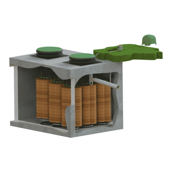
Certified Contractor Supplied Equipment as Specified by the Certified Designer on the Approved Plans 1. Approved tank. The Aero-Stream aerobic treatment unit works in conjunction with a septic tank and certified soil absorption field design. Site designer and contractor are responsible to provide the tank and soil absorption field as required in the approved plans. - Page 8 Figure 4, Picture of the AS500-1 System © Aero-Stream, LLC 2022 102822 Rev. F...
- Page 9 Figure 5, Picture of the AS500HO-1 System © Aero-Stream, LLC 2022 102822 Rev. F...
- Page 10 Figure 6, Picture of the AS650-1 System © Aero-Stream, LLC 2022 102822 Rev. F...
- Page 11 Figure 7, Picture of the AS750-1 System © Aero-Stream, LLC 2022 102822 Rev. F...
- Page 12 Figure 8, Picture of the AS1000-1 System © Aero-Stream, LLC 2022 102822 Rev. F...
- Page 13 Figure 9, Picture of the AS1500-1 System © Aero-Stream, LLC 2022 102822 Rev. F...
-
Page 14: Installation Process - Bio Brushes
Do not remove any cable ties from this assembly. TOP DOWN VIEW (Media fibers hidden for clarity) Diffuser Location Diffuser Location Figure 11, AS500-1 & AS500HO-1 Figure 12, AS650-1 FLOW © Aero-Stream, LLC 2022 102822 Rev. F... - Page 15 Figure 17 and 18 by crimping ears of clamp with Oetiker Tool or Side Cutters/Cutting Pliers. Figure 16, Bio-Brush Clusters Ballast Connection Tool Required: Oetiker 14100396 Pincer | Alternative: Side Cutters/ Cutting Pliers © Aero-Stream, LLC 2022 102822 Rev. F...
- Page 16 Bio-brushes about (1) inch long along the axis of each Bio-brush. Grasp the poly sleeve opposite of the slit and tear the sleeve downward until it is completely removed from the Bio- brush. Discard the poly sleeve. Repeat this for each Bio-brush. Figure 19, Bio-Brush Unwrapped © Aero-Stream, LLC 2022 102822 Rev. F...
- Page 17 (Figure 21) and feed each of the yellow float ropes through the lid of the tank. 5. For AS500-1, AS500HO-1 (Figure 11), AS650-1 (Figure 12), AS1000-1 (Figure 14), and AS1500-1 (Figure 15), the center-outlet side Bio-brush cluster should be slid over the center outlet housing as noted in Figure 20.
-
Page 18: Installation Process - Diffuser(S) And Air Line
(Cover & Safety Barrier hidden for clarity) Assemble Diffuser 2. Remove two-(2) stainless screws from center diffuser section. See Figure 24. Float Tube Ballast Tube (Top) (Bottom) Screw Screw Bottom Diffuser Stone Figure 24, Diffuser Overview © Aero-Stream, LLC 2022 102822 Rev. F... - Page 19 Stone Ballast Tube (Bottom) Figure 26, Float Tube Air Line Detail Figure 27, Diffuser Fully Assembled Repeat step 2 through step 4 as needed for models containing multiple diffuser assemblies (AS1000-1 and AS1500-1). © Aero-Stream, LLC 2022 102822 Rev. F...
- Page 20 When the diffuser hits the bottom of the tank, you will feel the air line become light. Diffuser should be in vertical position. Figure 28, Diffuser Installation inside Bio-Brush Cluster Diffuser Figure 29, Diffuser Installation inside Bio-Brush Cluster Note: Some Bio-Brush Fibers Hidden for Clarity © Aero-Stream, LLC 2022 102822 Rev. F...
- Page 21 6. Models AS500-1, AS500HO-1, AS650-1, and AS750-1. Insert the free end of the air line through the 5/8-inch hole from step 1 and pull the air line through the hole. Adequate air line of about 12 to 18 inches should be left inside the tank. The slack in the air line ensures that the diffuser assembly rests on the bottom of the tank.
- Page 22 Figure 32, Models AS500-1, AS500HO-1, AS650-1 &AS750-1 Figure 31, Model AS1000-1 Figure 34, Model AS1500-1 © Aero-Stream, LLC 2022 102822 Rev. F...
-
Page 23: Installation Process - Air Compressor
11. Layout the air line from steps 6 & 7 (tank to the air compressor). Do not connect the air line to the air compressor until completing the alarm installation. Peak performance is obtained when the air compressor is connected to the diffuser assembly with the shortest length of air line. © Aero-Stream, LLC 2022 102822 Rev. F... -
Page 24: Installation Process - Aero-Alert Alarm
FRONT VIEW Figure 36, Alarm and Float Switch Overview 13. Install the tee fitting in the output air line of the Aero-Stream unit (Figure 36). Secure the air line with provide cable ties. 14. Connect the 1/8-inch air line from the tee to the black barbed fitting on the bottom of the Aero-Alert (Figure 37). - Page 25 Slide the float clamp up or down so the bottom of the clamp is 2 inches below the water mark and tighten clamp. See Figure 41. © Aero-Stream, LLC 2022 102822 Rev. F...
- Page 26 10. Plug the free end of the float switch wire into the wire connector on the Aero-Alert. See Figure 43. Figure 43, Float Switch Connector (Left) and Aero-Alert Connector (Right) 11. Bury the float switch cord three-(3) to four-(4) inches below the ground surface. © Aero-Stream, LLC 2022 102822 Rev. F...
- Page 27 3. Install the effluent filter in the outlet tee baffle by sliding the filter into the cavity as shown in Figure 45. The filter must be in a vertical position as shown. Never install the filter horizontally in the outlet pipe leading to the dispersion component Figure 45, Filter Installation into Tee Baffle © Aero-Stream, LLC 2022 102822 Rev. F...
-
Page 28: Start-Up Procedure
Operation & Maintenance WARNING: Content in the following section pertains to certified Aero-Stream providers only! Property owners must contact the service provider listed on the front of this manual if product assistance is required. A property owner is not permitted to perform any diagnostics or product servicing. Failure to comply with these requirements is a violation of state and municipal codes. - Page 29 If service is required, call the authorized service provider listed on the label of the product or Aero-Stream. Attempts to service this product will void warranty and expose the user to electrical shock which may cause severe injury or death. Tampering will void warranty.
-
Page 30: Diagnostic Techniques
Intermittent Use or Vacating Property The AS500-1, AS500HO-1, AS650-1, AS750-1, AS1000-1, and AS1500-1 systems are designed to operate continuously. In the event the property is vacated for a period of 90 days or more, it is advised to turn off the power to the compressor. The compressor should be restarted upon occupancy of the premises. -
Page 31: Best Septic System Practices
To investigate a low air flow condition, disconnect the airline at the tee fitting after the alarm and measure the air pressure. The pressure should measure three-(3) to five-(5) psi. If the air pressure is below this range, contact Aero-Stream to obtain a RMA number to return the product for servicing. -
Page 32: Manufacturer's Limited Warranty
DISCLAIMER, DURATION, AND SCOPE OF THIS WARRANTY Aero-Stream, LLC (“Aero”) warrants its NSF/ANSI 40 Aerobic Treatment Units against defective materials or workmanship at the time of shipment for a period of 24 months. To make a valid claim under this warranty, Aero must be notified through writing, email or otherwise of any warranty claim within the applicable warranty period and in the manner described below. -
Page 33: Appendix
Sharon Steiner 734-827-6846 (phone) Business Unit Manager 734-827-7790 (fax) Wastewater Treatment Unit Program steiner@nsf.org (email) product specs (C0439427) P.O. Box 130140 Ann Arbor, MI 48113-0140 USA 734-769-8010 1-800-NSF-MARK Fax 734-769-0109 E-Mail: info@nsf.org Web:http://www.nsf.org © Aero-Stream, LLC 2022 102822 Rev. F... - Page 34 For the volume requirements and the performance of the larger systems it is at least proportionally equivalent to the NSF Certified Aero- Stream AS500-1 that is NSF Listed against NSF/ANSI Standard 40, Class II and the NSF Certified Aero-Stream AS500-2 and -3 that is NSF Listed to NSF/ANSI Standard 40, Class I. The manufacturer must ensure that the appropriate tankage is specified for the system.
- Page 35 Determining whether the requirements of the NSF Certification Policies for Wastewater Treatment Devices will continue to be met. Based on this review, NSF International can authorize the use of these additional tanks with the Aero- Stream AS500-1, AS500-2 and AS500-3 wastewater treatment systems ranging between 450 through 1500 (GPD). The performance anticipated will be adequate with this approval and is appropriate based off the volumes specified in the request and the additional justifications provided in the revised drawings.
- Page 36 NSF Certified Aero-Stream AS500-1 that is NSF Listed against NSF/ANSI Standard 40, Class II and the NSF Certified Aero-Stream AS500-2 and -3 that is NSF Listed to NSF/ANSI Standard 40, Class I. The manufacturer must ensure that the appropriate tankage is specified for the system. If you have any questions, please contact me directly.
- Page 37 ONE-(1) CHAMBER MODELS QTY. TANK(S) EACH AS500-1 - RMT-900-1 AS500-1 - RMT1000E-1 ROTH AS500-1 - RMT -1060-1 AS500-1 - 44463 or 42405 NORWESCO AS500-1 - 44473 AS500-1 - 43496 ACE ROTO MOLD AS500-1 - AST - 1000-1 AS500-1 - 43522...
- Page 38 AS750-1 - IM-1530-1 (Cluster Config 3x5+1x1) CHEMTAINER ROTH AS1000-1 - 42599 AS1000-1 - 44079 NORWESCO ACE ROTO MOLD SNYDER INDUSTRIES INFILTRATOR CHEMTAINER ROTH AS1500-1 - 44390 NORWESCO ACE ROTO MOLD SNYDER INDUSTRIES INFILTRATOR CHEMTAINER © Aero-Stream, LLC 2022 102822 Rev. F...
Need help?
Do you have a question about the AS500-1 and is the answer not in the manual?
Questions and answers