Table of Contents
Advertisement
Quick Links
8 PIN
INTERFACE
CONNECTOR
BNC
SENSOR
CONNECTOR
ELECTRONICS:
The connection of supply and outputs to the CAP04 is via 8 core screened cable. Connector
can accept cable up to 6.5 mm OD diameter. The supply is nominal 24VDC and
consumption current is less than 150mA.
Do not use same power supply with motors.
The all outputs are at normally low, 15V level during in active and drive up to 15mA.. These
outputs can directly drive LED or Opto Coupler. Due to current limiting, there is no need
voltage divider for 12 and 5 volts input range of your breakout board if inputs are opto
coupler isolated. Touch output can be adjusted internal trimpot as a minimum height. It
allows NULLING the height, if such feature required.
Voltage Control inputs are floating, with opto- coupler isolated. Inputs can be driven 0-10V
analogue output, however due to electrical noisy environment input has threshold level about
2-3V and range is 3-10V. It is also possible with external potentiometer (1K linear) as a
voltage divider for adjusting the height manually.
The diecast box must be grounded. Usually the sensor is bolted to the housing of torch lifter
and must be connected via thick wire 10mm² to System Ground to have a sufficient ground
connection. Use STAR type grounding. Interface cable shield should be connected at
system side.
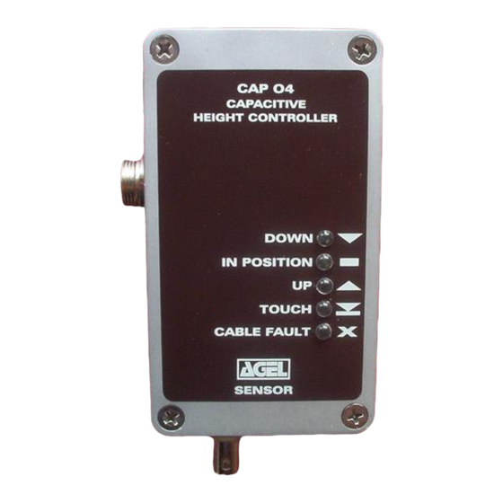
CAP 04
CAPACITIVE HEIGHT
CONTROLLER
DOWN
IN POSITION
UP
TOUCH
CABLE FAULT
Agelkom CAP04-V Manual
AGELKOM CAP04
Plasma and Oxy Fuel Torch height control
for sheet metal cutting machines
Height Sensor & Controller
Description:
SENSOR RING:
The metal sensor ring is connected to the CAP04 via a 90
cm long 75 ohms low capacitance coaxial cable. There is
a 2 size for Sensor Ring. The Plasma Ring ID is 34 mm
and OD is 47 mm. Sensing height of the ring should be
between 1,5 to 10 mm above the plate. The Fuel Ring ID
is 50 mm and OD is 69 mm . Sensing height of the oxy
ring should be between 7 to 35 mm above the plate The
ring must be insulated from all conductive parts of the
cutting torch.
the
1
Advertisement
Table of Contents

Related Manuals for AGELKOM CAP04

Summary of Contents for AGELKOM CAP04
- Page 1 SENSOR CONNECTOR ELECTRONICS: The connection of supply and outputs to the CAP04 is via 8 core screened cable. Connector can accept cable up to 6.5 mm OD diameter. The supply is nominal 24VDC and consumption current is less than 150mA.
- Page 2 Remove the front panel. Use plastic screw driver. Gently adjust of the internal coil of CAP04 sensor and observe down output is activated in your HOME position (or sufficiently high above the plate.) If DOWN LED is activated instead of UP readjust the core of the coil.
- Page 3 During thick plate cutting, dross may touch the sensor ring and the torch head lifted. To avoid this situation correct your cutting parameters for less dross. CAP04-V can be used with voltage controlled Height Control System. The two systems are OR’ed.
- Page 4 Simplified typical connection of CAP04-V shown below. SENSOR POWER +24VDC SENSOR POWER 0V CABLE SHIELD Breakout Board POWER SUPPLY / SYSTEM GROUND CABLE COLORS User defined PC Port# and pin# RED + 24v I/O board AGELKOM CAPACITIVE GREEN DOWN To PC, Port 2, pin # “Torch Down input”...
- Page 5 Connection Diagram: Only one output are shown. Cap04-V outputs are HIGH when activated. For UP, DOWN, TOUCH, CABLE FAULT are at 15V and 15mA. Check your input and configure for ACTIVE HIGH. Your inputs must be 0V level and Pull Up resistor not used .
- Page 6 Internal Coil Adjustment: Mount CAP04 and Sensor Head with Sensor Ring to your machine. Keep Sensor Ring to Working Plate distance at maximum (at least 10cm). Important: Do not turn more than ½ tour CW or CCW and do not apply force to the CORE of the internal coil.
- Page 7 Up Led is ON Fully CCW CW Coil MOUNTING GROUNDING Dimensions are in mm. Case Size 116*65*31 Two mounting holes are shown in Machine Chassis To System & Power Supply Box Use STAR type Ground Connection Use thick wire (10mm²) Agelkom CAP04-V Manual...
- Page 8 Mounting Details 67mm approx 47 mm dia. 69 mm dia. Agelkom CAP04-V Manual...
Need help?
Do you have a question about the CAP04 and is the answer not in the manual?
Questions and answers