Advertisement
Quick Links
Advertisement

Related Manuals for FRISKA Stockholm Corner Desk

Summary of Contents for FRISKA Stockholm Corner Desk
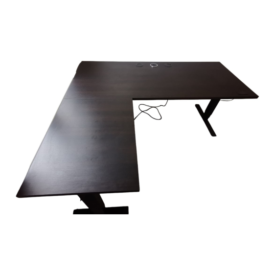
- Page 1 Stockholm Corner Desk Assembly...
- Page 2 SWITCH Basic control switch (optional) Memory control switch Packed with desktop ( x 5)
-
Page 3: Component List
FIXINGS *S - These screws for use in lieu of screw R when fixing a desktop without metal screw inserts. COMPONENT LIST A - Desk Legs B - Under-desk Support Arm C - Cross Beam Connectors D - Cross Beams E - Feet (690mm Long) F - Plastic inserts G - Power supply lead... - Page 4 ASSEMBLE THE MAIN FRAME SECTION Insert screws but do not tighten. Gap needed for frame and brackets in steps 3 and 5. ‘P’ x4 CAUTION Components are heavy – take care when handling ‘Q’ x4 Insert screws but do not tighten.
- Page 5 Fully tighten screws. ‘P’ x4 Do not tighten: Keep loose for step 5.
- Page 6 Unravel leg motor leads and push into plastic cable tidy slots...
- Page 7 Fully tighten screws. It may be necessary to use a soft headed mallet to fit tight fitting support arm onto the leg / frame.
- Page 8 Fully ‘Q’x8 tighten screws.
- Page 9 ‘W’ x4 Hand tighten fully into foot.
- Page 10 Slide 'C' into the gap between 'D' and 'F' - keep motor wires clear. Feed leg motor cables through centre hole...
- Page 11 Slide the second half of the frame as- sembly onto 'C' - keep motor wires clear Feed leg motor cables through centre hole CAUTION Frame is heavy – take care when positioning it.
- Page 12 ASSEMBLE THE RETURN FRAME SECTION Do not tighten: Keep loose for step 15. ‘P’ x4 CAUTION Components are heavy – take care when handling ‘Q’ x4 Insert screws but do not tighten.
- Page 13 Slide 'C' into the gap between 'D' and 'F'...
- Page 14 Fully tighten screws. Do not tighten: Keep loose for step 15.
- Page 15 Fully tighten ‘Q’x4 screws. Fully tighten screws. It may be necessary to use a soft headed mallet to fit tight fitting support arm onto the leg / frame.
- Page 16 ‘W’ x2 Hand tighten fully into foot.
- Page 17 RIGHT HAND RETURN Loosen screw to accept bracket Fully tighten screws. Place bracket (M) keyholes over the loosened frame screws and push the bracket to the right to secure the keyhole on the screws. For left hand returns, push the bracket (M) to the left.
- Page 18 Hook return leg assembly onto bracket as shown Feed cable extension 'N' through the frame to join with other cables. Left Hand Return...
- Page 19 NOTE Check desktop for any delivery damage before commencing this stage. NOTE Insert switch into aperture by applying firm, even pressure. Ensure correct orientation of switch within the aperture. Basic control has ‘UP’ stamped on the rear, position this furthest from the front edge. Left Hand Return...
- Page 20 Fully ‘R’x36 tighten screws. NOTE View is of underneath desk...
- Page 21 Fully tighten central cross beam screws. ‘Q’x8 IMPORTANT: Double check all screw are fully tightened. NOTE View is of underneath desk...
- Page 22 NOTE Fit the plastic caps to exposed frame screw heads. Press hard to locate the caps onto the screws and tap home securely using a mallet The caps are designed to mould onto the screws through force. ‘W’x20 NOTE View is of underneath desk...
- Page 23 Fully tighten screws. ‘R’x2 Fully tighten screws. ‘S’x8 NOTE View is of underneath desk...
- Page 24 Use cable clips 'J' to keep cables tidy. NOTE View is of underneath desk...
- Page 25 OPTIONAL CABLE TRAY NOTE! When mounting the cable tray on the 600mm deep return and using a monitor arm assembly, the cable tray will have to be mounted inside of the desktop support arms and fixed directly to the desktop with wood screws to allow clearance of the monitor arm fixing bracket.
- Page 26 Omit screws to fit Cable Tray. ‘T7’ x4 Fully tighten screws.
- Page 27 NOTE If using monitor arms with desk, set T3 bracket further from the back edge to give 80-100mm clearance Fully tighten screws. ‘T6’x4...
- Page 28 NOTE - Desk can be plugged into the optional power lead and hidden in cable tray.
-
Page 29: Reset Procedure
RESET PROCEDURE IMPORTANT! A reset procedure MUST be carried out immediately following assembly of the desk. • Lower the desk to its lowest position by pressing the down arrow on the hand control. • Release the button. • Press the button again and keep it pressed for 10 seconds •... - Page 30 SAVING A MEMORY POSITION Select desired height using the 'UP/DOWN' button. Press the 'SAVE' button followed by the memory number.
- Page 31 Friska Corner Desk Assembly Manual...
Need help?
Do you have a question about the Stockholm Corner Desk and is the answer not in the manual?
Questions and answers