Table of Contents
Advertisement
Quick Links
Advertisement
Table of Contents

Related Manuals for Innovista Sensors CROUZET TNi21 Series

Summary of Contents for Innovista Sensors CROUZET TNi21 Series
- Page 1 W W W.CROUZET-MOTOR S.C OM TNi21 DCMIND BRUSHLESS MOTORS USER AND SAFETY MANUAL...
- Page 2 TNi21 DCmind brushless motors User and safety manual Important notes This manual is part of the product. Read and follow the instructions in this manual. Keep this manual in a safe place. Give this manual and any documents relating to the product to anyone using the product. Read and follow closely all the safety instructions in the "Before you start - Safety information"...
-
Page 3: Table Of Contents
TNi21 Table of contents Introduction ..............................5 1.1. Motor family ............................5 1.2. Features ............................5 1.3. Options .............................. 5 1.4. Identification label ..........................5 1.5. Product coding ..........................6 Before you start - Safety information ......................7 2.1. Qualification of personnel ........................7 2.2. - Page 4 TNi21 8.1. Power connection ..........................27 8.1.1. Ballast circuit .......................... 27 8.1.2. Protection for EMC ......................... 29 8.2. Protective devices ........................... 30 8.2.1. Voltage protection........................30 8.2.2. Temperature protection ......................30 8.2.3. Current limiting ........................31 8.3. Connecting inputs/outputs....................... 31 8.3.1.
- Page 5 TNi21 About this manual This manual applies to TNI21 DCmind brushless products: 801400TNI21, 801495TNI21, 801496TNI21, 801410TNI21, 801800TNI21, 801896TNI21, 801897TNI21, 801810TNI21, 802800TNI21, 802896TNI21, 802897TNI21, 802810TNI21, Reference source for manuals Manuals are available to download from the Internet at the following address http://www.crouzet.com/ Units By default, units rotate anti-clockwise.
-
Page 6: Introduction
TNi21 1. INTRODUCTION 1.1. Motor family TNI21 DCmind brushless motors are direct current brushless motors with a built-in electronic control board. 1.2. Features TNI21 DCmind brushless motors are intelligent servomotors for speed and torque control applications. They are fitted with two unscreened cables as standard, one for power and one for control. 1.3. -
Page 7: Product Coding
TNi21 1.5. Product coding 80 XX XX TNI21: Product family based on TNI21 electronics PRODUCT REFERENCE Motor Type of stator: 14: 30 mm brushless stator 18: 50mm brushless stator 28: 50mm brushless stator high torque Gearboxes fitted: 00: no gearbox 10: RAD10 gearbox 95: P52 gearbox 96: P62 gearbox... -
Page 8: Before You Start - Safety Information
TNi21 2. BEFORE YOU START - SAFETY INFORMATION 2.1. Qualification of personnel Only qualified personnel, familiar with and understanding the contents of this manual, are authorised to work on and with this product. Qualified personnel should have a sound knowledge of current standards, regulations and requirements with regard to accident prevention, when carrying out work on or with the product. -
Page 9: Basic Information
TNi21 Basic information 2.3. DANGER DANGER DUE TO ELECTRIC SHOCK, EXPLOSION OR EXPLOSION DUE TO AN ELECTRICAL ARC • Only qualified personnel, familiar with and understanding the contents of this manual, are authorised to work on and with this product. Only qualified personnel are authorised to install, adjust, repair and maintain it. -
Page 10: Standards And Concepts
TNi21 WARNING LOSS OF CONTROL • When designing the control of the installation, the manufacturer should keep in mind the implications of a potential failure in control paths and, for certain critical functions, provide a method for returning to a safe state during and after the failure of a control path. -
Page 11: Precautions For Use At A Mechanical Level
TNi21 3. PRECAUTIONS FOR USE AT A MECHANICAL LEVEL 3.1. Data specific to the motor shaft 3.1.1. Force applied when pushing items on to the shaft WARNING MECHANICAL CHARACTERISTICS OF THE MOTOR Exceeding the maximum permitted force on the shaft will result in rapid wearing of the bearings, a broken shaft or the deterioration of any accessories (encoder, brake, etc.) •... -
Page 12: Options
TNi21 3.2. Options 3.2.1. Holding brake TNI21 DCmind brushless motors can be fitted with a fail safe electromechanical brake. The holding brake is designed to prevent the shaft from rotating when there is no power to the motor. The holding brake has no safety function. The "Connecting a holding brake"... -
Page 13: Installation
TNi21 4. INSTALLATION In a general sense, motors should be installed in line with good industrial practice. WARNING CONSIDERABLE WEIGHT AND FALLING PARTS The motor can weigh a lot. • Take the motor's weight into consideration when fitting it. • Fit the motor (tightening torque of screws) in such a way that it cannot come adrift, even in the event of high levels of acceleration or permanent vibration. - Page 14 TNi21 WARNING HOT SURFACES The metal surface of the product can reach more than 70°C during use. Avoid all contact with the metal surface. • Do not position inflammable or heat-sensitive components in immediate proximity. • Try to achieve an assembly that allows heat to dissipate efficiently. If these precautions are not taken, the result could be injury or damage to equipment.
-
Page 15: Snapshot Of The Installation Procedure
TNi21 4.1. Snapshot of the installation procedure The installation procedure is described in the follow sections: Electromagnetic compatibility, EMC Before fitting Fitting the motor Electrical installation Check that these sections have been read and understood and that, subsequently, the motor has been installed correctly. -
Page 16: Before Fitting
TNi21 4.3. Before fitting Look for damage Damaged drive systems should not be fitted or used. Check the drive system before fitting and look for visible signs of damage. Cleaning the shaft On leaving the factory, the ends of the motor shafts are coated with film of oil. Where transmission devices are to be fitted by bonding, it may be necessary to remove that oil film and clean the shaft. -
Page 17: Fitting The Motor
TNi21 4.4. Fitting the motor DANGER HOT SURFACES The surface of the motor can reach more than 70°C during use. • Avoid contact with hot surfaces. • Do not position inflammable or heat-sensitive components in immediate proximity. • Try to achieve an assembly that allows heat to dissipate efficiently. •... -
Page 18: Electrical Installation
TNi21 Installation position The motor can be installed in any position. Installation When fitting the motor on the flange, it must be aligned precisely, both axially and radially. All securing screws must be tightened to the torque prescribed by the application, taking care not to cause any warping. Fitting transmission devices Fitting transmission devices incorrectly could damage the motor. - Page 19 TNi21 WARNING OVER-VOLTAGES During braking phases, the motor generates over-voltages. • Check that these over-voltages are acceptable to other equipment connected to the same power supply. • Preferably use an external circuit, to limit over-volting In cases where braking is used intensively. If these precautions are not taken, the result could be death, serious injury or damage to equipment.
-
Page 20: Connecting The Holding Brake (Option)
TNi21 4.5.1. Connecting the holding brake (option) WARNING LOSS OF BRAKING FORCE DUE TO WEAR OR HIGH TEMPERATURE Application of the holding brake while the motor is rotating can cause rapid wear and loss of braking force. • Do not use the brake as a service brake. •... -
Page 21: Production Connector
TNi21 4.6. Production connector The motor is fitted with a silicone plug, as shown in the image below. It protects the connector used during the motor's manufacture. This connector is not intended to be accessed by users of the product. If the plug is removed, the motor will no longer be sealed, allowing fluids and particles to enter the motor, potentially destroying it or causing it to malfunction. -
Page 22: Switching On
TNi21 5. SWITCHING ON 5.1. Preparations for switching on Before switching on: Check that the mechanical installation is correct. Check that the electrical installation has been done professionally: in particular, check the connections on protective conductors and earth connections. Ensure that all connections are correct and sound and that screws are properly tight. - Page 23 TNi21 WARNING FALLING PARTS Reactive torque could cause the motor to move, tip or fall. • Secure the motor firmly, so that it cannot come loose due to severe acceleration. If these precautions are not taken, the result could be death, serious injury or damage to equipment.
-
Page 24: Product Presentation
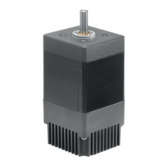
TNi21 6. PRODUCT PRESENTATION 6.1. Description of the product No power rear brake Label Power supply (Optional) (Power and Logic) TNI21 integrated electronics 8-contact logic connector (Inputs/Outputs) Brushless motor Output axis Figure 4 6.2. TNI21 control electronics The TNI21 electronic board contains control electronics for brushless motors and is built into the body of the motor. -
Page 25: Technical Characteristics
TNi21 7. TECHNICAL CHARACTERISTICS 7.1. Electrical data Maximum product characteristics Parameters Value Unit Supply voltage V DC_MAX Maximum current I DC_MAX Maximum voltage at the inputs V IN_MAX Maximum voltage at the outputs V OUT_MAX Maximum current at the outputs I OUT_MAX Operating characteristics Parameters... -
Page 26: Control Logic Bundle
TNi21 7.3. Control logic bundle Comprises a UL-approved cable, style 2464 80°C 300V, 500mm long as standard, fitted with a Molex connector reference 43025-0800 8 contacts: Figure 5 Function Colour of wires (AWG24) Input no.1 – On / Off Vert / Green Input no. -
Page 27: Power Supply Cable
TNi21 7.4. Power supply cable Function Colour of wires (AWG16) Power supplied: +12V DC → +32V DC Marron / Brown Power earth: 0V DC Bleu / Blue The power supply cable is UL-approved style 2517 105°C 300V, 500mm long as standard. Where a cable extension is used, the cross-section of the cable used must be of sufficient size for the current consumed and the length of cable. -
Page 28: Motor Electrical Connection
TNi21 8. MOTOR ELECTRICAL CONNECTION 8.1. Power connection We recommend that the motor frame is earthed. Diagram showing power connections. Rated voltage DCmind DCmind Motor Motor (n) Figure 7 Fit capacitors to smooth out inrush current. Recommended value 1000µF per Amp consumed. Optional. - Page 29 TNi21 8.1.1.1. Proposed ballast circuit diagram. The arrangement below dissipates braking energy into a resistor, thus limiting the over-voltage at the motor terminals. Figure 8 8.1.1.2. Sizing resistor R12 (R Ballast The lower the resistor value, the higher the braking current. Typical values are in the region of several Ohms. Where V is the speed of rotation in rpm and J the inertia in kg.m².
-
Page 30: Protection For Emc
TNi21 8.1.1.3. Selecting the cut-off voltage The cut-off voltage should be selected: According to the power supply According to other devices connected to the same power supply. If your power supply does not tolerate current feedback, fit a diode in series upstream of the ballast circuit to protect it. -
Page 31: Protective Devices
TNi21 8.2. Protective devices DANGER PROTECTIVE DEVICES The product includes internal protection devices which cut the power supply to the motor, when activated. Since the motor is no longer being controlled, driving forces may drop. • The manufacturer of the system is responsible for complying with all the safety rules applicable in the event of product failure. -
Page 32: Current Limiting
TNi21 8.2.3. Current limiting The product has an internal current limiter. This limiter operates directly on the motor through hardware. The limiter automatically clips the current to the peak current value in the motor phases. If the limit is reached, the motor's performance is reduced. This product is not designed to operate continuously at this limit (see the "Electrical data"... -
Page 33: Equivalent Outputs Diagram
TNi21 8.3.2. Equivalent outputs diagram PNP outputs to 50mA max. open slip-ring Fit a pull-down resistor (recommended value 4.7 kΩ). CAUTION EARTHING THE OUTPUTS The accidental earthing of the outputs or connecting them to a capacitive load will result in them being destroyed. Before powering up the motor, check that the outputs are wired correctly. -
Page 34: Operating Mode
TNi21 9. OPERATING MODE 9.1. Preliminaries DCmind motors with TNI21 integrated electronics are designed to operate by regulating the speed with an adjustable torque limiter. These electronics operate in trapezoidal switching mode. There are two types of board available in the catalogue: Version with proportional 0-10V inputs Version with proportional PWM inputs The speed is controlled by a factory-set PID to allow a wider operating range. -
Page 35: Function E4 - Torque Limiter Set-Point
TNi21 9.2.4. Function E4 - Torque limiter set-point The torque limiter proportional input is linear throughout its range. The corresponding scale varies according to the type of motor: Drive basis Min terminal (0V or 0%) Max terminal (10V or 100%) 80140_TNI21 360 mN.m 35 mN.m... -
Page 36: Safe Mode
TNi21 9.4. SAFE mode Motors with TNI21 integrated electronics have a SAFE mode. If power to the motor is cut, no holding torque is applied (free shaft) SAFETY Range limit Action 110°C Stop Excessive temperature Re-start necessary 90°C OK to run Stop Under-voltage Re-start necessary... -
Page 37: Service, Maintenance And Problem Solving
TNi21 11. SERVICE, MAINTENANCE AND PROBLEM SOLVING 11.1. Addresses of after-sales service points Contact your distributor The list of distributors can be accessed via the Crouzet Automatismes web site www.crouzet.com 11.2. Storage Motors should only be transported and stored in a dry environment, free from dust and protected from vibration. -
Page 38: Replacing The Motor
TNi21 The holding brake is bedded in before it leaves the factory. If the holding brake is not called upon to do any mechanical work for a long period, some of its parts could corrode. If the holding brake does not provide the holding torque specified in its technical characteristics, it might be necessary to bed it in again. -
Page 39: Terms And Abbreviations
TNi21 11.6. Terms and abbreviations Level of protection The level of protection is a standardised rating used for electrical equipment ans intended to describe the protection against the ingress of solids and liquids into the motor enclosure, e.g. IP54M. The M indicates that testing was done with the motor running.
Need help?
Do you have a question about the CROUZET TNi21 Series and is the answer not in the manual?
Questions and answers