Table of Contents
Advertisement
Advertisement
Table of Contents

Related Manuals for M&R Challenger 2


Summary of Contents for M&R Challenger 2
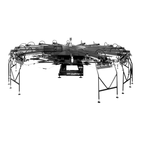
- Page 1 V.033114 Part # MAN-CHALLENGERII Challenger II Jv1 $95.00 USD...
- Page 2 V.033114 This page intentionally left blank M&R Companies 1N 372 Main St. Glen Ellyn, IL 60137 USA Tel: +630-858-6101 Fax: +630-858-6134 www.mrprint.com | store.mrprint.com...
-
Page 3: Table Of Contents
V.033114 Table of Contents Safety and Operational Guidelines ........................... 5 Management Responsibilities ........................... 6 Operator Responsibilities ............................7 General Information ..............................8 Service and Parts ..............................9 Defined Purpose ..............................10 Warranty ..................................10 Product Specifications .............................11 Compressed Air Supply ............................12 Screen Placement Grid ............................13 Operation ...................................14 Main Control Panel ..............................15 6.1.1... - Page 4 V.033114 This page intentionally left blank M&R Companies 1N 372 Main St. Glen Ellyn, IL 60137 USA Tel: +630-858-6101 Fax: +630-858-6134 www.mrprint.com | store.mrprint.com...
-
Page 5: Safety And Operational Guidelines
V.033114 Safety and Operational Guidelines DANGER This symbol identifies situations that endanger people, property, and/or equipment. If such conditions exist, the equipment must be shut down and all energy sources (electrical, gas, and pneumatic) must be disconnected, purged, and locked out until the problem is resolved. Never attempt to bypass or defeat any safety device. -
Page 6: Management Responsibilities
V.033114 Management Responsibilities 1. Ensure that this equipment is used only for the purposes set forth in the “Defined Purpose” Management Responsibilities section of this manual. 2. Ensure that all employees involved with the operation of this equipment or working near it read, understand, and act in accordance with the operational and safety standards set forth in this manual, including the Operator Responsibilities listed below. -
Page 7: Operator Responsibilities
V.033114 Operator Responsibilities Note: ‘Operator Responsibilities’ pertain to all employees who work on or near the equipment; this includes, but Operator is not limited to those who clean, maintain and repair the equipment as well as those who operate it. In Responsibilities general, all those who work on or near the equipment have a duty to use reasonable and ordinary care for their own safety when in the vicinity of the machine. -
Page 8: General Information
V.033114 General Information This Document This document is based on information available at the time of its publication. While every effort has been made to be accurate, the information contained herein does not purport to cover all details or variations in hardware, software, features, or specifications, or to provide for every possible contingency in connection with installation, operation and maintenance. -
Page 9: Service And Parts
V.033114 Service and Parts Manufacturer’s Most products manufactured by the M&R Companies carry a metal manufacturer’s rating plate similar Rating Plate to the one shown below. Please use it to fill out the product information below, and be prepared to provide the identification information when calling. -
Page 10: Defined Purpose
V.033114 Defined Purpose Textile Presses Textile Presses are designed to print textile inks on textile substrates, as more fully set forth in the manual specific to that product. Any other use of this equipment is not permitted. Textile Dryers Textile Dryers are designed to cure/dry textile inks on textile substrates, as more fully set forth in the manual specific to that product. -
Page 11: Product Specifications
V.033114 Product Specifications Specifications Challenger II Challenger II Challenger II Challenger II Challenger II 12/10 14/12 16/14 18/16 20/18 Air @ 6.9 Bar 510 l/m (18 cfm) 595 l/m (21 cfm) 595 l/m (21 cfm) 595 l/m (21 cfm) 595 l/m (21 cfm) (100 psi) Diameter 518 cm (17') -
Page 12: Compressed Air Supply
V.033114 Compressed Air Supply Description Compressor Chiller Unit Shut-Off Valve Closed Loop Supply Lines (Air Drops) to Other Equipment (If Required) Drain with Shut-Off Valve Supply Line (Air Drop) to Equipment (3/4” inside-diameter pipe required) Filter/Regulator/Lubricator Flexible Rubber Hose Equipment This illustrates a typical closed-loop compressed air supply system. -
Page 13: Screen Placement Grid
V.033114 Screen Placement Grid Textile presses are shipped with a Screen Placement Grid as shown above. This is a useful tool for screen placement between the film positive and the screen. M&R Companies 1N 372 Main St. Glen Ellyn, IL 60137 USA Tel: +630-858-6101 Fax: +630-858-6134 www.mrprint.com | store.mrprint.com... -
Page 14: Operation
V.033114 Operation Cycle Yellow Cycle Interruption Cords are provided to restrict Interruption access into the index table operating area while the Cords equipment is in operation. To disconnect, grasp each of the cords at the magnetic jack connection and pull apart. Emergency The red EMERGENCY STOP Button is provided to stop all Stop Button... -
Page 15: Main Control Panel
V.033114 Main Control Panel Number Name Function Print Permits manual cycling of an individual print station. The Print button is also Button used during screen frame setup to check registration. During setup, press the Print button. The index carousel moves up so that screen registration or placement may be checked. - Page 16 V.033114 Number Name Function Print Start / This switch is provided as a convenience when initially starting or finishing a print Print Finish run. It is designed to eliminate the need to individually turn on or off print Switch stations. Placing this switch in the Print Start position will automatically command each print station that is selected to On, to print sequentially at the start of a print run.
-
Page 17: Operator Interface
V.033114 6.1.1 Operator Interface Operator The Operator Interface touch screen is used to Interface access and adjust all functions of the press. When electrical power is turned ON to the equipment, the M&R screen is displayed. In the lower right is the Menu button and in the lower left is the INFO button. - Page 18 V.033114 Counters The counters menu is accessed by pressing the Counters button on the Menu screen. The counters menu contains six menus: Shift, Job, Total, Preset, Remaining and Speed. Shift Counter Shift indicates the total number of press cycles during a given production shift. To reset the Shift, press the data entry cell to the right of Shift;...
- Page 19 V.033114 Preset The Preset counter is used to enter a number of print cycles for a given print job. For example, if a print job consists of printing 30 dozen (360) shirts, enter 360. You may enter up to a maximum of 32,767 print cycles into the Preset menu The minimum is 0.
- Page 20 V.033114 can record the production levels and use this information to estimate future production times for this particular job. Press the Back Arrow to return to the MENU screen. Timers Press the Timers button on the Menu screen. The Timers menu contains five menu items: Index, Flash, Quartz, Delay and Preheat.
- Page 21 V.033114 Delay Delay controls the dwell time of the quartz lamps as the index table starts its index motion. This additional delay time allows the quartz lamps to reach operating power and reduces overexposure of heat sensitive substrates. To adjust the Delay, press the data entry cell to the right of Delay;...
- Page 22 V.033114 Multi-Print The first menu selection in the Heads menu is Multi-Print. Multi-Print Up/Down commands the print carousel to remain in the Up (print) position until all print strokes are completed. When selected to Down, the print carousel lowers to the index position when the last print head completes the print stroke for the first print.
- Page 23 V.033114 Inkdip Every The Inkdip Every control automatically scoops ink (US Patent No. from the rear ink well area of the screen into the 5,649,479) active image area of the screen. Press the data entry cell to the right of Inkdip Every; a numeric keypad is displayed.
- Page 24 V.033114 In the Enhanced mode, the print stations may be On or Off. Pressing the PRINT button momentarily on the main control panel or at any of the print station control panels commands the index carousel to move up to the upper (print) position. When the PRINT button is pressed and held for 2- 3 seconds, the print station performs a complete print cycle, (flood, index table up, print, index table...
- Page 25 V.033114 Index Index dwell time is the time interval during automatic operation in which the system operator may load and/or unload garments. This time interval starts after the index table has reached the fully raised position at the conclusion of the index motion, and ends with the start of the index table start cycle.
- Page 26 V.033114 Print Head Located just below the Revolution number menu Program item is a reference line listing each of the print Indicators heads. Below each of the numbers is a letter or number that indicates how the print head will perform in a given revolution in the Revolver Program.
- Page 27 V.033114 Alarm Enabled Alarm Enabled provides the system operator with a way to either enable or disable the audible alarm signal which sounds just before the completion of a programmed Revolver print sequence. Press the button to change between Alarm Enabled and Alarm Disabled. Stop Alarm The Stop Alarm button is used to silence the audible alarm signal that sounds just before the...
- Page 28 V.033114 Servo Offset The Servo Offset sets the stopping position of the indexer servo drive as it aligns with the index registration forks. Servo Offset also adjusts the index stop after changing pallets to a smaller or larger size. Larger pallets increase the index load, while smaller lighter pallets decrease the index load.
- Page 29 V.033114 Low Oil The oil level in the oil reservoir for the index servo Indexes drive system is monitored by a sensor which alerts the operator to insufficient oil for lubrication. The oil level may be monitored using the Low Oil Indexes menu selection.
- Page 30 V.033114 Mega-Stamp Down Time is used to select the amount of time Down Time that the Mega-Stamp heat platen is down in contact with the foil and garment. To adjust the Down Time, press the data entry cell to the right; a numeric keypad is displayed.
- Page 31 V.033114 Mega-Stamp The next menu is Mega-Stamp Down. The menu Down is displayed in red so it is an output signal. The illustration shows that the proximity switch which is used to confirm Mega-Stamp Down is currently OFF. When the proximity switch is actuated the indication will display ON.
- Page 32 V.033114 Flashes Flashes is used to designate infrared flash position. To access the Flashes menu, press the Flashes button on the Options menu screen. Flashes selects the print head location where a flash unit will operate in the print flash sequence. Flash Location To select a print head to operate as a flash cure station, first place the FRONT/REAR switch for...
- Page 33 V.033114 Quartz Time Quartz controls the time the Quartz Flash heating elements are on. To adjust the Quartz dwell time, press the data entry cell to the right of Quartz; a numeric keypad is displayed. Enter the time in seconds and then press Enter. The maximum Quartz Time is 15 seconds and the minimum is 0 seconds.
- Page 34 V.033114 Delay The next menu selection in the FLASHES menu is Delay. The Delay menu is used to control the preheat time for the M&R standard Quartz flash units. During normal operation, the quartz flash heating elements are energized as the pallets begin their index cycle.
- Page 35 V.033114 Preheat This menu item is used to control the preheat time for the Quartz Flash panels used on your system. Press the data entry cell to the right of Preheat; a numeric keypad is displayed. Enter the Preheat time in seconds and then press Enter. The maximum Preheat time is 15 seconds, the minimum is 0 seconds.
- Page 36 V.033114 right of Spray Every; a numeric keypad is displayed. Enter the number from 1 to 99 and then press Enter. Your selection for Spray Every is now displayed in the data entry cell. Front Delay (3) Front Delay permits the system operator to program a time delay interval, in hundreds of a second, before activation of the Annamister system.
- Page 37 V.033114 Revolution # Revolution # gives the system operator a visual indication of the current revolutions remaining before the M&R Annamister automatically applies adhesive to the pallets, as determined by the setting in the Spray Every menu. Pallet # (8) Pallet # provides the number of remaining pallets before the M&R Annamister automatically applies adhesive.
- Page 38 V.033114 Hardware Test The HARDWARE TEST screen includes the test menus: PANEL TEST, PROX TEST, OTHER TESTS, INDEX MOTION, INDEX SERVO and INDEX SERVO HISTORY. Panel Test The PANEL TEST screen provides a visual indication of all the switches used on the main control panel.
- Page 39 V.033114 Front/Rear The next row of switches is the FRONT/REAR Switches switches. The FRONT/REAR switches are shown in the REAR position on the PANEL TEST screen. To test any of the switches place the switch in the FRONT position. The switch on the screen moves to the FRONT position and the color changes to red.
- Page 40 V.033114 Emergency The EMERGENCY STOP button is shown in the Stop Button (4) activated or in position on the PANEL TEST screen. To test, turn the EMERGENCY STOP button to the right. The button increases in diameter confirming its deactivation. If you push the button in, the EMERGENCY STOP button switch decreases in diameter on the screen confirming its operation.
- Page 41 V.033114 Index On The Index On proximity switch is mounted to the Proximity indexer base and is positioned so that it reads the cam follower bearings on the carousel plate as the indexer revolves. When this proximity switch is actuated, the control system then raises the index carousel up into the registration forks and print position.
- Page 42 V.033114 Double Index The Double Index Fork Proximity switch is Fork Proximity mounted to the index base near the load and Switch unload stations and is positioned so that it reads the double index fork when the double index fork is retracted.
- Page 43 V.033114 HARDWARE TEST menu. Index Motion To access the INDEX MOTION screen, press the Information INDEX MOTION button on the HARDWARE TEST screen. As the servo drive operates, it maintains communication with the PLC. The motion card sends and receives signals from the servo drive that constantly monitors the position and speed of the servo drive.
- Page 44 V.033114 Alarms To access the Alarms screen, press the Alarms button on the Menu screen. If an alarm condition is detected from the previous production run or production day, the Alarm indication (alarm bell) appears in the upper right corner of the display window. This condition alerts the operator that an Alarm condition exists, and that operation of the system is not possible.
- Page 45 V.033114 Date/Time To set the time and date, press the Date/Time button at the bottom of the Service Data screen. This will display the Date/Time screen. The screen displays the date as Month, Day and Year and the time using a 24 hour clock where 13:00 hours is read as 1:00 PM in the afternoon.
- Page 46 V.033114 When you are finished cleaning the screen surface, press the top corner buttons simultaneously. This will return you to the Service Data screen. Video Contrast The Video menu is used to adjust the brightness and the contrast of the display screen. To access the Video menu press the Video button on the Service Data menu screen.
- Page 47 V.033114 M&R To access the M&R Information menu, press the Information M&R button on the Menu screen. The M&R Information screen contains information on how to contact M&R Printing Equipment and program information. Press the Back Arrow to return to the M&R screen.
-
Page 48: Revolver Sequencing Program Overview
V.033114 6.1.2 Revolver Sequencing Program Overview Revolver Textile Screen Printers may have print Sequencing requirements beyond the capabilities of their Program equipment. However, the flexibility and versatility U.S. Patent No. of the screen printing process allows 5,595,113 experimentation with such variables as color sequence, ink deposit and flash cure utilization. - Page 49 V.033114 Step 2 Now go to OPTIONS and press REVOLVER (4). The button (5) to the right of Revolver Mode displays either On or Off. To change between On and Off mode press the button. Press the button until On displays to program or operate in the Revolver Mode.
- Page 50 V.033114 Press Enter Program (8). The indicator below print head No. 1 displays a 1 and below print head No. 2 the screen displays the letter F confirming that the print head will now operate as a flash cure station. Turn head No.
- Page 51 V.033114 Step 6 Select Revolution No. 3. Press the data entry cell (6) to the right of Revolution; a numeric keypad displays. Enter the number 3 and press Enter. Step 7 Under Revolution No. 3 select heads 2 and 6 to On (7).
- Page 52 V.033114 You are now ready to print. Place the Automatic/Manual switch (10) in the Automatic position. Activate the Print Start switch (9) to begin the Revolver sequence. To continue printing: When you hear the audible alarm near the end of the last revolution push the Print Start switch (9).
-
Page 53: Print Station
V.033114 Print Station 6.2.1 Print Station Control Panel Number Name Function Squeegee/ Locks the squeegee/floodbar to its mounting bar. To lock the Floodbar squeegee/floodbar to the print station carriage mounting bar, position Lock/Unlock the squeegee/floodbar on the mounting bar and place the switch in the Lock position. - Page 54 V.033114 Number Name Function Squeegee Speed The Squeegee Speed knob controls the squeegee speed. Turn the knob clockwise to increase speed. Turn the knob counterclockwise to decrease speed. Print Button Cycles the individual print station manually. The Print button is also used during screen frame setup to check registration.
-
Page 55: Install Pallets And Screen Frames
V.033114 6.2.2 Install Pallets and Screen Frames WARNING: Before entering between print heads, always push in Emergency Stop button and disconnect Cycle Interruption Cords. Refer to the beginning of this section for detailed information. Install Pallets Loosen the handle (1) on the top of the Pallet Locator (2). - Page 56 V.033114 Install Screen For easy installation of screen frames, and/or Frames flash cure units, the M&R print stations feature a Flip Up Front Frame Holder which pivots up and out of the way. To move the front frame holder up to the load position, unlatch the front frame holder lock handle (1).
-
Page 57: Squeegee/Floodbar
V.033114 Pull up on the red locking lever (1) to secure the front frame holder. Place the FRONT FRAME LOCK switch on the print head control panel in the ON position. 6.2.3 Squeegee/Floodbar WARNING: Before entering between print heads, always push in Emergency Stop button and disconnect Cycle Interruption Cords. - Page 58 V.033114 WARNING: Before entering between print heads, always push in Emergency Stop button and disconnect Cycle Interruption Cords. Refer to the beginning of this section for detailed information. Squeegee/ Adjust the floodbar pressure using the knobs at Floodbar the top of the print carriage assembly. The Pressure floodbar pressure should be adjusted so that there Adjustments...
-
Page 59: Print Head Adjustments
V.033114 6.2.4 Print Head Adjustments WARNING: Before entering between print heads, always push in Emergency Stop button and disconnect Cycle Interruption Cords. Refer to the beginning of this section for detailed information. Print Head Place the switch for the rear screen frame clamps Micro Register on the print head control panel in the OFF position. - Page 60 V.033114 WARNING: Before entering between print heads, always push in Emergency Stop button and disconnect Cycle Interruption Cords. Refer to the beginning of this section for detailed information. Rear Micro The rear micro-register adjustment allows Register movement of the screen frame from the left to the Adjustment right.
-
Page 61: Central Off-Contact Lever
V.033114 6.2.5 Central Off-Contact Lever WARNING: Before entering between print heads, always push in Emergency Stop button and disconnect Cycle Interruption Cords. Refer to the beginning of this section for detailed information. Central The Central Off-Contact Lever provides a single point to change the off-contact dimension of Off-Contact all the screens with the adjustment of a lever. -
Page 62: Scheduled Maintenance
V.033114 Scheduled Maintenance Benefits Properly maintained equipment operates more efficiently, reduces operating costs, and lasts longer. A properly managed preventive maintenance program can minimize downtime. Preparation An effective preventive maintenance program includes: proper selection, handling, and application of lubricants ... - Page 63 V.033114 Frequency Maintenance Daily Check Index Drive Lubricator Oil Level (Cont.) Items required: 1 - Vactra No. 4 Oil (M&R Part No. 7017018) IMPORTANT: Under normal operating conditions, the oil level in the reservoir should gradually decrease over time. If the oil level does not decrease, contact the M&R service department.
- Page 64 V.033114 Frequency Maintenance WARNING: To prevent possible injury to personnel and/or damage to the equipment, lock out and tag the electrical service and compressed air supply to the equipment. Lubricate Index Clevis Fork, Clevis Plate and Lower Weekly Carousel Plate Items required: 2 - 4"...
- Page 65 V.033114 Frequency Maintenance Weekly Lubricate Index Needle Bearing (Cont.) Items required: 1 - Permatex Super Lube with Teflon Grease (M&R Part No. 7018034) 1 - Standard Pump Action Grease Gun Using a standard pump action grease gun, slowly apply 1 pump of grease to the grease fitting (1).
- Page 66 V.033114 Frequency Maintenance WARNING: To prevent possible injury to personnel and/or damage to the equipment, lock out and tag the electrical service and compressed air supply to the equipment. Monthly Clean Circulation Fan and Air Vents Items required: 1 - Vacuum Vacuum the area around the fresh air intake vent, circulation fan and finger guard assembly (1).
- Page 67 V.033114 Frequency Maintenance WARNING: To prevent possible injury to personnel and/or damage to the equipment, lock out and tag the electrical service and compressed air supply to the equipment. Every Lubricate Micro-Registration Threaded Shafts Three Months 1 - Permatex Super Lube with Teflon Grease (M&R Part No.
- Page 68 V.033114 Frequency Maintenance Every Replace Air Filter Element and Reservoir Seal Three Months Items required: (Cont.) 1 - Filter Element (M&R Part No. 2019114-A) 1 - Bowl Seal (M&R Part No. 2020091-1) 1 - 10 wt. Non-Detergent Oil (M&R Part No. 7017000) 1.
- Page 69 V.033114 as shown. IMPORTANT: Do not use pry bars or other tools as levers to move the Print Carriage Drive Assembly. 4. While holding the Print Carriage Drive Assembly in position, tighten the three socket cap screws (1). Frequency Maintenance WARNING: To prevent possible injury to personnel and/or damage to the equipment, lock out and tag the electrical service and compressed air supply to the equipment.
- Page 70 V.033114 Frequency Maintenance Every 3. Remove the old battery (3) from the holder, then, disconnect Three the battery by squeezing while pulling on the connector (4). Years (Cont.) 4. Install replacement battery. Replace PLC Battery Items required: 1 - PLC Battery (M&R Part No. 1017515) IMPORTANT: This procedure requires electrical power to be connected to the press.
- Page 71 V.033114 Frequency Maintenance Every 4. Install replacement battery. Three Years (Cont.) Replace Operator Interface Battery Items required: 1 – Battery (M&R Part No. 1017786) 1 - Blade Screwdriver Note: Replace battery when the LOW battery indicator is displayed. IMPORTANT: The new battery must be installed within twenty seconds of removal of the old battery.
-
Page 72: Scheduled Maintenance Log
V.033114 Scheduled Maintenance Log Date Maintenance Procedure performed/ Initials Check and Clean Print Carriage Assembly Drain Air Filter Moisture Trap Lubricate Index Clevis Fork, Clevis Plate and Lower Carousel Plate Lubricate Index Needle Bearing Lubricate Center Shaft Bushings Lubricate Print Carriage Assembly Linear Bearing Lubricate Registration Cam Follower Bearings and Forks... -
Page 73: Replacement Parts
V.033114 Replacement Parts CE vs. UL All equipment containing electrical components is designed to comply with either Conformance Models European (CE) or Underwriters Laboratories (UL) standards, and each type of equipment has a different parts list. CE equipment runs at 50 Hz; UL equipment runs at 60 Hz. Electrical specifications, including Hertz, can be found on the Manufacturer’s Rating Plate similar to the one shown below. - Page 74 V.033114 Control Panel (UL & CE) Part Numbers Control Panel (UL & CE) Part Name All Models Push Button Switch 1017159 Switch (Single/Multi) 1017157 Switch (Test Print) 1010011 Switch (Print Start/Print Finish) 1010007A Emergency Stop Push Button (must also order 1010040B) 1010040 1017717 Operator Interface...
- Page 75 V.033114 Electrical Cabinet (UL) Part Numbers Electrical Cabinet (UL) Part Name 12/10 14/12 16/14 18/16 20/18 Servo Amplifier 1017483 1017483 1017483 1017483 1017483 Replacement Battery 1017147 1017147 1017147 1017147 1017147 Power Supply 1024131 1024131 1024131 1024131 1024131 Safety Relay (K2) 1017422 1017422 1017422...
- Page 76 V.033114 Electrical Cabinet (CE) Part Numbers Electrical Cabinet (CE) Part Name 12/10 14/12 16/14 18/16 20/18 Servo Amplifier 1017595 1017595 1017595 1017595 1017595 Replacement Battery 1017147 1017147 1017147 1017147 1017147 Power Supply 1024131 1024131 1024131 1024131 1024131 Safety Relay (K2) 1017422 1017422 1017422...
- Page 77 V.033114 Varistor 1023009 1023009 1023009 1023009 1023009 Line Filter 1036020A 1036020A 1036020A 1036020A 1036020A Varistor 1023001 1023001 1023001 1023001 1023001 Vent Fan 1009004 1009004 1009004 1009004 1009004 Note: 380-415V 3Ph. 50Hz. shown. Refer to Schematic Diagrams for Electrical Parts at the beginning of this section before placing a parts order.
- Page 78 V.033114 Carriage Assembly (UL & CE) Carriage Assembly (UL & CE) Part Numbers Part Name All Models Carriage Plate 9157902 Bulkhead Fitting 5/32OD X 1/8 NPT 2003239 Fitting Grease 1/8 NPT 45 DEG 2003032 Head Proximity Flag 9157934 Linear Bearing Carriage 3030113 Grease Nipple M6 X 4.5 mm 2005129...
- Page 79 V.033114 Bearing Casting Assembly (UL & CE) Bearing Casting Assembly (UL & CE) Part Numbers Part Name All Models Register Bearing Bracket 8362408 Cam Follower 3023012A Split Lock Washer ZP 5/8" 3022005 Fin Hex Nut ZP 5/8-18 3013016 Fin Hex Jam Nut ZP 3/8-16 3013014 Socket Cap Screw 3/8-16 X 2”...
- Page 80 V.033114 Carriage Drive Assembly (UL & CE) Carriage Drive Assembly (UL & CE) Part Numbers Part Name All Models Gear Motor Mounting Bracket 9157917-A Keystock 6mm X 6mm X 0.55" 9165543-A Pulley Shaft Washer 1" OD 9165502 Keystock 6mm X 6mm X 1.125" 9165544 External Retaining Ring 18mm Shaft 3024072...
- Page 81 V.033114 Front Micro Assembly (UL & CE) Front Micro Assembly (UL & CE) Part Numbers Part Name All Models Top Micro Casting 9150061 Plastic Washer 9165542 Flanged Bronze Bearing 1/2" X 3/4" X 5/8" 3023025 Micro Positioning Plate 9150014 Lock Clamp Spacer Plate 9150017 Clamp 3033087...
- Page 82 V.033114 Hex Cap Screw 3/8-24 X 1-1/4" 3054031 Micro X - Y Adjustment Screw 8090057 Finish Hex Jam Nut 3/8-24 3013015 Micro Side Adjustment Screw 8090056 Micro Lock Washer 2" OD 8080132 Elastic Stop Nut ZP 3/8-16 3012003 Top Lock Washer 9150016 Female Handle 3032001...
- Page 83 V.033114 Rear Screen Holder Assembly (UL & CE) Rear Screen Holder Assembly (UL & CE) Part Numbers Part Name All Models SAE Washer ZP 1/2" 3021000 Rear Screen Holder 9159053 Double Acting Air Cylinder 2009023B Fitting Male Swivel Elbow 10-32 2003031 Socket Cap Screw 8-32 X 5/8"...
- Page 84 V.033114 Threaded Rod 3/8-16 X 3.5" 8090143-1 Right Hand Rear Micro Clevis 1/2-20 9362062 Knob Bracket Insert 3/16" 9362111 Socket Set Screw 1/4-20 X 3/8" 3007003 Hex Jam Nut 1/2-20 3013023 Shoulder Screw Spacer 9362579 Left Hand Rear Micro Clevis 9362061 Finish Hex Jam Nut ZP 3/8-24 3013015...
- Page 85 V.033114 Front Screen Holder Assembly (UL & CE) Front Screen Holder Assembly (UL & CE) Part Numbers Part Name All Models Front Screen Holder 9159051-A Key Locking Insert 3/8-16 3013106 Double Acting Air Cylinder 2009023B Fitting Male Swivel Elbow 10-32 2003031 Socket Cap Screw 8-32 X 5/8"...
- Page 86 V.033114 Carriage Proximity Bracket Assembly (UL & CE) Carriage Proximity Bracket Assembly (UL & CE) Part Numbers Part Name All Models Energy Chain Guide 9157991 Energy Chain Mounting Bracket 1017430 Snap-Open Energy Chain 1017431-2 Head Stroke Proximity Mounting Bracket 9155692 Rubber Grommet 13/16"...
- Page 87 V.033114 Head Tube Assembly (UL & CE) Part Numbers Head Tube Assembly (UL & CE) Part Name 10/12 14/12 16/14 18/16 20/18 Support Beam Extrusion 9157904 9157904 9157904 9157904 9157904 Front Spacer 9150906 9150906 9150906 9150906 9150906 Linear Rail 3030114 3030114 3030114 3030114...
- Page 88 V.033114 Snap In Plug 13/16" Hole Diameter 7025023 7025023 7025023 7025023 7025023 AC Head Control Box 9163081-B 9163081-B 9163081-B 9163081-B 9163081-B Head Control Box Cover 9163074-A 9163074-A 9163074-A 9163074-A 9163074-A SAE Washer 5/16" 3021023 3021023 3021023 3021023 3021023 Rubber Grommet 1-3/8" OD 7001028 7001028 7001028...
- Page 89 V.033114 Optional Pressure Equalizer Assembly (UL & CE) Optional Pressure Equalizer Assembly (UL & CE) Part Numbers Part Name All Models Print Head Cover 9165547-A Pressure Regulator With Gauge 2019132 M&R Companies 1N 372 Main St. Glen Ellyn, IL 60137 USA Tel: +630-858-6101 Fax: +630-858-6134 www.mrprint.com | store.mrprint.com...
- Page 90 V.033114 Head Support Assembly (UL & CE) Head Support Assembly (UL & CE) Part Numbers Part Name All Models Head Support Frame 9132296 Leveling Foot 3037001 M&R Companies 1N 372 Main St. Glen Ellyn, IL 60137 USA Tel: +630-858-6101 Fax: +630-858-6134 www.mrprint.com | store.mrprint.com...
- Page 91 V.033114 Pneumatic Squeegee Floodbar Assembly (UL & CE) Optional Pneumatic Squeegee Floodbar Assembly (UL & CE) Part Numbers Part Name All Models Squeegee\Floodbar Mounting Tube 9165526 Squeegee\Floodbar Holder, Left 9165525 Squeegee\Floodbar Holder, Right 9165524 Squeegee\Floodbar Air Clamp Cylinder 9162041 Socket Cap Screw 5/16-24 X 1/2" 3009133 Shoulder Bolt 5/16"...
- Page 92 V.033114 Filter Regulator Assembly (UL & CE) Filter Regulator Assembly (UL & CE) Part Numbers Part Name All Models Filter Regulator Lubricator 3/4" 2020091-AA Replacement Filter (Not Shown) 2019114-A Hose 3/4" I.D. 3058043-A M&R Companies 1N 372 Main St. Glen Ellyn, IL 60137 USA Tel: +630-858-6101 Fax: +630-858-6134 www.mrprint.com | store.mrprint.com...
- Page 93 V.033114 Chassis Assembly (UL & CE) Chassis Assembly (UL & CE) Part Numbers Part Name All Models Sub Base 9150426 Bearing Header Ring 9150124 Bearing Cup 9150125 Bearing Cone 3023001 Lift Cylinder 2009302C Finish Hex Nut 1/2-13 3013027 Base Side Cover 9150376-R Leveling Bolt 9370109...
- Page 94 V.033114 Main Control Panel Assembly (UL & CE) Part Numbers Main Control Panel Assembly (UL & CE) Part Name 12/10 14/12 16/14 18/16 20/18 Control Box Arm Weldment 9153706 9150385 9150385 9150585 9150036 Control Box Weldment 9150381 9150381 9150381 9150381 9150381 Control Box Hanger 9150460...
- Page 95 V.033114 Chopper Valve Assembly (UL & CE) Part Numbers Chopper Valve Assembly (UL & CE) Part Name 12/10 14/12 16/14 18/16 20/18 Valve Assembly (Complete) 2010050C 2010049C 2010048C 2011014C 2011019 Solenoid Valve 2010093 2010093 2010093 2010093 2010093 Fitting Male Elbow 1/8 NPT, 3/8" Tube 2003146 2003146 2003146...
- Page 96 V.033114 Off-Contact Assembly (UL & CE) Off-Contact Assembly (UL & CE) Part Numbers Part Name All Models Selector Lever 9150358 Off-Contact Parallel Lever 8080236 Off-Contact Stringer 8080238 Off-Contact Regulator 8051244-A Off-Contact Down Plate 9150363 Off-Contact Down Plate #1 8051232 Off-Contact Lock 9150364 Lift Cylinder Extension 9150362...
- Page 97 V.033114 Front Drive Motor Ball Screw Assembly (UL & CE) Front Drive Motor Ball Screw Assembly (UL & CE) Part Numbers Part Name All Models Left Hand, Bearing Block 9131376 Ball Screw Bumper 9150424 Distance Bushing 9105258 Single Row Angular Contact 3023089 Bearing Flange 9105252...
- Page 98 V.033114 Back Drive Motor Ball Screw Assembly (UL & CE) Back Drive Motor Ball Screw Assembly (UL & CE) Part Numbers Part Name All Models Right Side Bearing Block 9131377-A Ball Screw Bumper 9131384 Ball Screw Shaft 9150441 Reinforcement Plate 9131374 Indexer Nut Housing-Finish 9131365...
- Page 99 V.033114 Finish Hex Jam Nut 1/4-20 3013114 Fork Clevis Cylinder 1-1/16" X 3" 2009016 Universal Flow Control 1/4" 2018079 Grommet Rubber 1-1/8" OD X 5/8" 7001016 Home Proximity Mounting Bracket 9131382 Home Proximity Mounting Bracket 9150429 Snap Action Switch Roller Type 1020242 Needle Roller Bearing 3023460...
- Page 100 V.033114 Carriage Drive Idler Pulley Assembly (UL & CE) Carriage Drive Idler Pulley Assembly (UL & CE) Part Numbers Part Name All Models Front End Plate 9157909 Idler Roller Shaft 9165532 Idler Roller 9150907 Bearing 3023097 External Retaining Ring 3024041 Socket Cap Screw 5/16-18 X 1"...
- Page 101 V.033114 Pallet Stop Assembly (UL & CE) Part Numbers Pallet Stop Assembly (UL & CE) Part Name 10/12 14/12 16/14 18/16 20/18 Pallet Stop Mounting Bracket 9153039-A 9150858-A 9150138-A 9150538-A 9130050 Pallet Stop Mounting Bar 9153707 9150857-B 9150137-A 9150137-A 9172473 Plastic Adjustment Handle Male 3033033 3033033...
- Page 102 V.033114 Index Base Assembly (UL & CE) Index Base Assembly (UL & CE) Part Numbers Part Name All Models Ball Screw Drive Base Weldment 9150431 Indexer Support 9150438 Fitting Male Elbow 3/8" 2003002 Linear Way Slide With 2 Blocks 3030085 Oil Splash Shield 9150407 Fitting, Elbow 1/8 NPT M6 X.75...
- Page 103 V.033114 Double Index Assembly (UL & CE) Double Index Assembly (UL & CE) Part Numbers Part Name All Models Double Index Base Weldment 9151141 Double Index Fork Bracket 9151145 Double Index Nylon Fork 9150151 Double Index Cylinder Bracket 9151144 Pivot Bracket 2009232 Female Rod End 5/16-24 3034001...
- Page 104 V.033114 Socket Cap Screw 3/8-16 X 1" 3009000 Double Index Proximity Mounting Bracket 9150153 Round Proximity Switch M12 X 1" 1010223 Washer 9151167 Hex Nut ZP 5/16-24 3013032 Oil Panel Assembly (UL & CE) Oil Panel Assembly (UL & CE) Part Numbers Part Name All Models...
- Page 105 V.033114 Spider Arm Assembly (UL & CE) Part Numbers Spider Arm Assembly (UL & CE) Part Name 12/10 14/12 16/14 18/16 20/18 Spider Arm Weldment 9153705 9150813 9151917 9153370 9172371 Button Socket Cap Screw 3/8-24 X 2" 3001210 3001210 3001210 3001210 3001210 Pallet Support Bracket...
- Page 106 V.033114 Carousel Assembly (UL & CE) Part Numbers Carousel Assembly (UL & CE) Part Name 12/10 14/12 16/14 18/16 2018 Top Cover 9153037-A 9150847-A 9150099-A 9150599-A 9130042 Center Top Cover 9153036-A 9150849-A 9150097-A 9150597-A 9130039 Head Lock Plate 9150318 9150318 9150318 9150318 9150318...
Need help?
Do you have a question about the Challenger 2 and is the answer not in the manual?
Questions and answers