Table of Contents
Advertisement
Advertisement
Table of Contents

Related Manuals for M&R Starlight A50


Summary of Contents for M&R Starlight A50
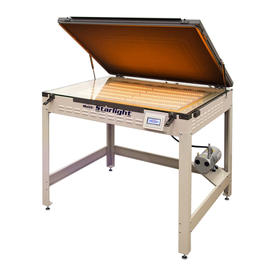
- Page 1 Starlight Ev1 Part # MAN-STARLIGHT $95.00 USD V.113017...
-
Page 3: Table Of Contents
V.113017 Contents Safety and Operational Guidelines Management Responsibilities ........................5 Operator Responsibilities ......................... 6 General Information Service and Parts ............................. 8 Defined Purpose ............................9 Warranty ..............................10 Specifications Assembly and Installation Level Unit and Connect Pump ......................... 12 Assemble Optional Frame ........................14 Operation Starlight 3140 and Starlight ASO Control Screen .................. -
Page 4: Safety And Operational Guidelines
V.113017 1. Safety and Operational Guidelines DANGER This symbol identifies situations that endanger people, property, and/or equipment. If such conditions exist, the equipment must be shut down and all energy sources (electrical, gas, and pneumatic) must be disconnected, purged, and locked out until the problem is resolved. Never attempt to bypass or defeat any safety device. -
Page 5: Management Responsibilities
V.113017 1.1 Management Responsibilities Ensure that this equipment is used only for the purposes set forth in the “Defined Purpose” section of this manual. Ensure that all employees involved with the operation of this equipment or working near it read, understand, and act in accordance with the operational and safety standards set forth in this manual, including the Operator Responsibilities listed below. -
Page 6: Operator Responsibilities
V.113017 1.2 Operator Responsibilities Note: 'Operator Responsibilities' pertain to all employees who work on or near the equipment; this includes, but is not limited to those who clean, maintain and repair the equipment as well as those who operate it. In general, all those who work on or near the equipment have a duty to use reasonable and ordinary care for their own safety when in the vicinity of the machine. -
Page 7: General Information
V.113017 2. General Information This Document This document is based on information available at the time of its publication. While every effort has been made to be accurate, the information contained herein does not purport to cover all details or variations in hardware, software, features, or specifications, or to provide for every possible contingency in connection with installation, operation and maintenance. -
Page 8: Service And Parts
V.113017 2.1 Service and Parts Manufacturer's Rating Plate Most products manufactured by the M&R Companies have a metal manufacturer's rating plate. Below is a label imprinted with the information from your product's rating plate. Please be prepared to provide this information when calling. -
Page 9: Defined Purpose
V.113017 2.2 Defined Purpose Textile Presses Textile Presses are designed to print textile inks on textile substrates, as more fully set forth in the manual specific to that product. Any other use of this equipment is not permitted. Textile Dryers Textile Dryers are designed to cure/dry textile inks on textile substrates, as more fully set forth in the manual specific to that product. -
Page 10: Warranty
V.113017 2.3 Warranty Limited Warranty Your Warranty does not apply to damages sustained due to equipment misuse, whether intentional or negligent, and such misuse may void your warranty. Misuse includes - but is not limited to - the items listed below. In addition, M&R Printing Equipment, Inc. -
Page 11: Specifications
V.113017 3. Specifications Specifications Starlight 2331 Starlight 3140/ASO 110 V, 1 ph, 9.5 A, 50/60 Hz, 1.1 110 V, 1 ph, 12.5 A, 50/60 Hz, 1.4 Electrical Requirements Maximum Screen Frame 58 x 79 cm (23" x 31") 79 x 102 cm (31" x 40") Size Overall Size with Stand (H 104 x 109 x 91 cm (41"... -
Page 12: Assembly And Installation
V.113017 4. Assembly and Installation Inspection Carefully inspect crates for signs of damage in transit. If equipment has been damaged in transit, notify the Freight Carrier immediately. M&R is not responsible for damage that occurs during transportation. Safety Precautions M&R encourages the use of a licensed electrician for the installation of electrical service to this equipment. The equipment must be electrically grounded in accordance with local codes, or in the absence of local codes, with the National Electrical Code ANSI/NFPA 70 –... - Page 13 V.113017 Attach both the vacuum hoses from the vacuum blanket to the barbed hose fittings (1) at the rear of the unit. Connect the vacuum tube to the barbed hose fitting (1) on the vacuum pump. Connect the electric power cord from the vacuum pump to the receptacle (2) at the rear of the vacuum frame base.
-
Page 14: Assemble Optional Frame
V.113017 4.2 Assemble Optional Frame Install Leveling Foot (1) in each leg (2). Using a 5/32" hex wrench, assemble sides and back (3) to legs (2) using 1/4" lock washers (4) and 1/4 x 5/8" long button socket cap screws (5). Install shelf (6) on the top of the side supports (3) using the four self-tapping screws (7). - Page 15 V.113017 Attach Unit to Base Position base close to where it will be used. Using two persons lift unit (1) and put it on the base (2). Attach unit to base with 3/8" lock washer (3) and 3/8 x 5/8" socket cap screw (4). Attach legs to unit using 1/4"...
-
Page 16: Operation
V.113017 5. Operation 5.1 Starlight 3140 and Starlight ASO Control Screen Vacuum and exposure times are entered through a keypad on the Main screen and up to 24 jobs can be saved in the memory. Vacuum or exposure times are started and stopped using the control screen. 5.2 Making Screen Exposures 5.2.1 Loading Screen Unlatch the blanket frame assembly by pulling the bottom latch forward and up. - Page 17 V.113017 Raise the blanket frame to the load/unload position. Center your film positive and screen frame on the glass work surface. Place the bleeder cords on the screen as close to the edge as possible. Note: DO NOT LAY THE BLEEDER CORDS ON THE IMAGE AREA. Lower the blanket frame assembly and latch it by reversing the procedure described in Step 1.
-
Page 18: Exposing With The Control Screen
V.113017 5.2.2 Exposing With the Control Screen The screen is on when power is supplied to the unit. Touch the screen to activate the Main screen. After unlatching the blanket frame assembly, the Frame Open screen displays. Press INSPECT ON to turn on inspection lights to check screen location or for any screen imperfections. -
Page 19: Saving And Recalling Jobs
V.113017 5.2.3 Saving and Recalling Jobs Press SAVE on the Main screen to save a job. Up to 24 jobs, each with a unique name, description or job number can be saved and recalled. Press SAVE after entering the vacuum and exposure times to view the SAVE TO menu. -
Page 20: Starlight Cts Conversion Kit
V.113017 6. Starlight CTS Conversion Kit Items Required: 1 - Phillips Screwdriver 1 - 1/8" Hex Wrench Part Numbers CTS Conversion Kit Part Name 2331 3140 Front and Rear Bar 9N0600322 9N0700322 Side Bar 9N0600323 9N0700323 Shelf Tray 9N0600343-1 9N0700343-1 Wall Tray 9N0600343-2 9N0700343-2... -
Page 21: Starlight Cts Conversion
V.113017 6.1 Starlight CTS Conversion Converting a Version 2 Starlight unit to CTS compatibility. Note: With the glass removed your exposure times are quicker, so testing is necessary to find the optimum exposure times. Note: Version 2 units have internally mounted Fans (1). Power Off (2) the Starlight and disconnect the main incoming power source (3). - Page 22 V.113017 Assemble the Frame Support using the four Screws (5). Attach one rod Support Bracket (6) to the end of each Support Rods (7). Slide the black Support Trays (8) onto the Support Rods (7) with vertical edges towards the end of the support rods, and install the remaining two Support Brackets (6) on the other end of the Support Rods Set the assembled frame work in the chassis and center it front to rear and right to left.
- Page 23 V.113017 When setting the support frame into the chassis the front right corner depresses a sensor switch (9). This changes the internal electronics to respond when the vacuum lid is opened. There are holes pre-punched in each corner of the chassis. The support frame is secured using Self Tapping Screws (10).
- Page 24 V.113017 With the Glass removed there is a void created that must be filled. The tan colored frame assembly is made for that purpose. Position the tan frame pieces (11), (12) on a flat table and assemble them at each corner using the corner Mounting Brackets (13) with the supplied Screws (14). Set the Frame into the chassis where the glass used to be and re-install the Hold Down Brackets (4).
-
Page 25: Scheduled Maintenance
V.113017 7. Scheduled Maintenance Benefits Properly maintained equipment operates more efficiently, reduces operating costs, and lasts longer. A properly managed preventive maintenance program can minimize downtime. Preparation An effective preventive maintenance program includes: proper selection, handling, and application of lubricants ... - Page 26 V.113017 Clean Glass Items required: 1 – Glass Cleaner Spray the glass surface (1) with glass cleaner and use a towel to wipe down. Weekly WARNING: To prevent possible injury to personnel and/or damage to the equipment, lock out and tag the electrical service to the equipment. Inspect Vacuum Hoses Inspect the vacuum hose (1) from the vacuum pump to the vacuum frame for any sign of twisting, kinking, or wear.
-
Page 27: Scheduled Maintenance Log (Based On A 40 Hour Work Week.)
V.113017 7.1 Scheduled Maintenance Log (Based on a 40 hour work week.) Date Maintenance Procedure performed/ Initials Inspect and Clean Vacuum Blanket Clean Glass Inspect Vacuum Hoses M&R Companies 440 Medinah Rd. Roselle, IL 60172 USA Tel: +630-858-6101 Fax: +630-858-6134 www.mrprint.com | store.mrprint.com... -
Page 28: Replacement Parts
V.113017 8. Replacement Parts CE vs. UL Models All equipment containing electrical components is designed to comply with either Conformance European (CE) or Underwriters Laboratories (UL) standards, and each type of equipment has a different parts list. CE equipment runs at 50 Hz; UL equipment runs at 60 Hz. Electrical specifications, including Hertz, can be found on the Manufacturer’s Rating Plate similar to the one shown below. - Page 29 V.113017 Starlight Chassis and LED Assembly (UL & CE) Part Numbers Chassis and LED Assembly (UL & CE) Part Name 2331 3140 Blanket Assembly 9N0600407 9N0100601 Corner Glass Left Bracket 9N0101032 Screw 10X.50 PC59 Glass 9N1400409 9N0107001 Magnet Mounting Plate Assembly 9N0600335 9N0600335 Lift Arm...
- Page 30 V.113017 Starlight ASO Chassis and LED Assembly (UL & CE) Chassis and LED Assembly (UL & CE) Part Numbers Part Name Blanket Assembly 9N0100601 Corner Glass Left Bracket 9N0101032 Screw 10X.50 PC59 Glass 9N0107001 Magnet Mounting Plate Assembly 9N0600335 Lift Arm PR10 Leg Equalizer Glide 3037009...
- Page 31 V.113017 Vacuum Pump (UL & CE) Vacuum Pump (UL & CE) Part Numbers Part Name First Light Hose Connector 3/8” ID VH590 Muffler 1/4” 2014000 Vacuum Relief Valve VH1008 Close Pipe Nipple VH126 Reducer 3/8 – 1/4” VH899 Pipe Tee 1/4" VE123 Vacuum Pressure Sensor 1024200/201...
- Page 32 V.113017 Controller (UL & CE) Controller (UL & CE) Part Numbers Part Name All Models Touchscreen Controller 1017812 M&R Companies 440 Medinah Rd. Roselle, IL 60172 USA Tel: +630-858-6101 Fax: +630-858-6134 www.mrprint.com | store.mrprint.com...
- Page 33 V.113017 Electrical (UL & CE) Part Numbers Control Panel (UL & CE) Part Name 2331 3140 Rubber Tubing 3/8" ID VH895 VH895 Circuit Breaker 10A 2331 1004719 Circuit Breaker 20A 3140 1004716 Breaker Guard 9N0700341 9N0700341 Receptacle,4 Pin for Pressure Sensor 10160114 10160114 1009000...
- Page 34 V.113017 Base Assembly (UL & CE) Part Number Base Assembly (UL & CE) Part Name 2331 3140 9N0600226 9N0600226 Floor Stand Leg 9N0600227 9N0700227 Side Brace 9N0600228 9N0700228 Back Brace 3037009 3037009 Leg Equalizer Glide 9N0700229 9N0700229 Pump Support Bracket 3022001 3022001 Split Lock Washer ZP 1/4"...
- Page 35 V.113017 LED Cabinet on Base (UL & CE) Part Number LED Cabinet on Base (UL & CE) Part Name 2331 3140 LED Cabinet Assembly 9N0600101 9N0700101 SAE Washer 1/4" 3021015 3021015 Split Lock Washer ZP 1/4" 3022001 3022001 Button Socket Cap Screw 1/4-20 X 5/8" 3001080 3001080 Split Lock Washer ZP 3/8"...
- Page 36 V.113017 M&R Companies 440 Medinah Rd. Roselle, IL 60172 USA Tel: +630-858-6101 Fax: +630-858-6134 www.mrprint.com | store.mrprint.com...
Need help?
Do you have a question about the Starlight A50 and is the answer not in the manual?
Questions and answers