Table of Contents
Advertisement
Quick Links
Advertisement
Table of Contents

Summary of Contents for Optimal Audio SmartAmp
- Page 1 USER GUIDE SmartAmp Amplifiers with DSP Amplifiers >...
- Page 2 SmartAmp Amplifiers with DSP Amplifiers Congratulations on your choice of Optimal Audio for your latest sound system installation. The Optimal Audio range of compatible audio zoners, controller, amplifiers and loudspeakers are designed to work together simply and effectively. Our quick start...
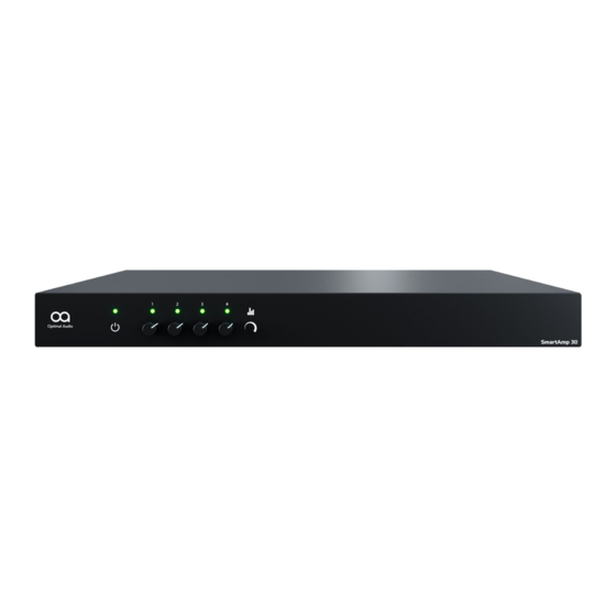
- Page 3 SmartAmp Amplifiers with DSP Amplifiers There are three amplifiers in the SmartAmp range: SmartAmp 10 Two channels of Class D amplification, 125W each with power sharing, low impedance or 70 – 100V output, integrated DSP SmartAmp 20 Four channels of Class D amplification, 125W each with power sharing between pairs of channels, low impedance or 70 –...
- Page 4 Presets can be found later in this • Connect the output of your Optimal Audio Zone 4 or 8 that relates to the guide. loudspeakers in the area you want your SmartAmp to power SmartAmp 10 and 20 offer increased flexibility through power sharing between •...
- Page 5 SmartAmps are Energy Star compliant and will sleep when not in use to minimize energy consumption. On receiving a signal at the input above SmartAmp amplifiers have no mains power switch and are operational as -47dBu the amplifier will wake up.
-
Page 6: Rear Panel Connections & Controls
3 & 4 USER GUIDE Introduction Overview Start using Power up Rear panel Inputs Outputs Dip switches < > © 2021. Optimal Audio Group Ltd. (v1.0) GPIO Installation Maintenance Tech specs Appendix A Appendix B Appendix C Safety info 6/20... -
Page 7: Input Connections
Amplifiers with DSP Amplifiers Input Connections SmartAmp inputs are of balanced, line level format and require the use of suitable two-core, screened signal cable. Input connections to SmartAmp are achieved via male ‘Euro Block’ connectors. Connecting cables to the supplied female input connectors is illustrated below... -
Page 8: Loudspeaker Outputs
Be aware that the Hi-Z output pins can deliver voltages up to 100 volts! Output connections from SmartAmp are achieved via male ‘Euro Block’ Ch1: Low-Z connection connectors. Ensure that speaker connection polarity is correct throughout... -
Page 9: Dip Switches
1 1 1 1 1 1 High-Z 100V Reserved Reserved Reserved Reserved Reserved Reserved Low-Z 4 ohms SmartAmp 10, 20 and 30. Be DIPS Low-Z 4 ohms Reserved Reserved Reserved Reserved Reserved Reserved 2 2 2 2 2 2... - Page 10 SmartAmp Amplifiers with DSP Amplifiers GPIO (General Purpose In/Out ) Connections The GPIO connectors enable remote control of key parameters of SmartAmp: Function Notes GPIO GND (1) Ground reference for all GPIO pins GPIO v12 (2) * Channel 1 & 2 auxiliary gain Connect to a potentiometer (>10kΩ) wiper between...
-
Page 11: Installation & Rack Mounting
SmartAmp 30 showing rack ears and with the rear support attached Installation & Rack Mounting Optimal Audio provide a set of hardware options for rack mounting SmartAmp in SmartAmp 30 is shipped with rack mount ‘ears’ attached as illustrated above and several ways. - Page 12 Amplifiers Installation & Rack Mounting SmartAmp 20 is shipped without rack mount hardware attached but can be In addition to rack mount ears, optional rack mount rear support hardware is configured for rack installation using one standard rack ‘ear’ and one half-rack available and can be attached to the amplifier.
- Page 13 Free-standing plate. If not to be installed in an equipment rack, SmartAmp can be placed free- SmartAmp 10 is also shipped without rack mount hardware attached but can be standing on a flat surface. Adhesive rubber feet are supplied for this purpose.
-
Page 14: Maintenance
Amplifiers with DSP Amplifiers Maintenance Your Optimal Audio SmartAmp should require minimal maintenance and prove to be a reliable workhorse in your sound system From time to time it may be necessary to clean the fan filters. SmartAmps are forced air cooled, and if located in certain environments the filters can become blocked, causing the amplifier to run at high temperatures, with the potential for shut down. - Page 15 2 x 125W 4 x 125W 4 x 250W DIGITAL SIGNAL PROCESSING EQ & limiter presets for Optimal Audio loudspeakers EQ & limiter presets for Optimal Audio loudspeakers EQ & limiter presets for Optimal Audio loudspeakers COOLING Forced air cooling with fan...
- Page 16 M3 x 6 Black USER GUIDE Introduction Overview Start using Power up Rear panel Inputs Outputs Dip switches < > © 2021. Optimal Audio Group Ltd. (v1.0) GPIO Installation Maintenance Tech specs Appendix A Appendix B Appendix C Safety info 16/20...
- Page 17 M4 x 8 USER GUIDE Introduction Overview Start using Power up Rear panel Inputs Outputs Dip switches < > © 2021. Optimal Audio Group Ltd. (v1.0) GPIO Installation Maintenance Tech specs Appendix A Appendix B Appendix C Safety info 17/20...
- Page 18 Torx Screw Countersink M3 x 6 Black USER GUIDE Introduction Overview Start using Power up Rear panel Inputs Outputs Dip switches < > © 2021. Optimal Audio Group Ltd. (v1.0) GPIO Installation Maintenance Tech specs Appendix A Appendix B Appendix C Safety info 18/20...
-
Page 19: Important Safety Instructions
17. Do not remove any covers, loosen any fixings or allow items to enter any aperture. USER GUIDE Introduction Overview Start using Power up Rear panel Inputs Outputs Dip switches < > © 2021. Optimal Audio Group Ltd. (v1.0) GPIO Installation Maintenance Tech specs Appendix A Appendix B Appendix C Safety info 19/20... - Page 20 Relax, It’s Optimal Audio. optimal-audio.co.uk Optimal Audio Group Ltd. Century Point, Halifax Road, Cressex Business Park, High Wycombe, Buckinghamshire, HP12 3SL...


Need help?
Do you have a question about the SmartAmp and is the answer not in the manual?
Questions and answers