
Related Manuals for Soltronics LTG-CF5002

Summary of Contents for Soltronics LTG-CF5002
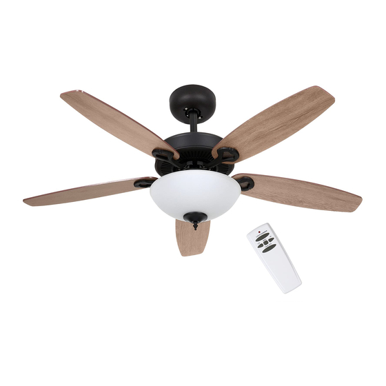
- Page 1 CEILING FANS INSTALLATION INSTRUCTION MODEL SERIES LTG-CF5002 READ AND SAVE THESE INSTRUCTIONS...
-
Page 2: Safety Precautions
SAFETY PRECAUTIONS Before beginning installation of your new ceiling fan, read and follow these safety precautions. If you are not familiar with national and local electrical codes and basic electrical wiring procedures, we recommend that you have a qualified electrician install your new ceiling fan. Before you begin, TURN OFF THE ELECTRICITY. - Page 3 This ceiling fan was not designed for installation in any location where it might be exposed to moisture or high humidity. Installation in this type of location could be UNSAFE, will most likely damage the fan and its finish... and will VOID YOUR WARRANTY. Every effort has been made to provide you with proper instructions for the safe installation of this ceiling fan.
-
Page 4: Preparing For Installation
PREPARING FOR INSTALLATION Unpack and inspect fan carefully to be certain all contents are included. Turn off power at fuse box to avoid possible electrical shock. Use metal outlet box suitable for fan support (must support 35 lbs). Before attaching fan to outlet box, ensure the outlet box is securely fastened by at least two points to a structural ceiling member (a loose box will cause the fan... -
Page 5: Install Mounting Bracket
INSTALL MOUNTING BRACKET Install the mounting bracket onto the electrical junction box in the ceiling Junction Box using two machine screws, two wash- ers and two lock washers. The mounting bracket has slotted holes to enable it to move sideways for proper alignment. - Page 6 DOWNROD PREPARATION Remove clamp pin (1) and cross pin (2) from downrod (3). Loosen set screws in downrod coupling. Insert down rod through the canopy and coupling cover (4) as shown above. Insert motor wires through the down rod and insert the down rod into the down rod coupling. Make sure to align the hole in the downrod with the hole in the downrod coupling.
- Page 7 HANGING THE FAN BODY Notice the half ball on the end of Mounting Bracket the support rod is grooved down Keyway Pin one side. This Keyway fits over the small keyway pin on the inside of the mounting bracket and keeps Ball Hanger the ceiling fan from spinning on the mounting bracket.
-
Page 8: Wire Connection
WIRE CONNECTION Use wire connnectors to connect household supply and receiver wires Black (hot/power) according to the diagram and the White (neutral) following steps: Bare/Green (ground) • Connect the green wire from the downrod and mounting bracket to the Bare/Green (ground) supply wire. -
Page 9: Blade Installation
BLADE INSTALLATION Attach blade brackets to blades using the blade bracket screws (1), metal washers (2), and fabric washers (3), if provided. NOTE: Some models do not utilize fabric washers (3). Check the motor for plastic shipping stabilizer tabs (1), and remove them if they are present. -
Page 10: Light Fixture Installation
LIGHT FIXTURE INSTALLATION Connect the plugs from the upper and lower switch housings.Then install three of the switch housing screws. - Page 11 LIGHT FIXTURE INSTALLATION...
- Page 12 REMOTE INTALLATION 1. SETTING THE CODES This unit has 16 different code combinations. To set the codes, perform the following steps: Setting the codes on the transmitter: a. Remove battery cover. Press firmly on the arrow and slide battery cover off. b.
-
Page 13: Remote Operation
REMOTE OPERATION 1.OPERATING TRANSMITTER: A. Install 9 volt battery(not included). (To prevent damage to transmitter, remove the battery if not used for a long time). B. Store the transmitter away from excessive heat or humidity. C. This remote control unit is equipped with 16 code combinations. In order to prevent possible interference from or to other remote units such as garage door openers, car alarm or security system. -
Page 14: Parts Inventory
PARTS INVENTORY ______ Hanging Bracket ______ Receiver of Remote Control ______ Canopy ______ 4 in & 6 in Downrods ______ Yoke Cover Cross Pin ______ ______ Motor Assembly Blade x5 Blade Arms x5 ______ Light Kit x2 ______ Led Bulb x2 ______ Glass Shade Gaskets... -
Page 15: Problem Solution
PROBLEM SOLUTION 1. Fan will not start: Check circuit fuses or breakers. Check all electrical connections to insure proper contact.CAUTION: Make sure the main power if OFF when checking any electrical connection. 2. Fan sounds noisy: Make sure all motor housing screws are sung. Make sure the screws that attach the fan blade brackets to the motor are tight.
Need help?
Do you have a question about the LTG-CF5002 and is the answer not in the manual?
Questions and answers