
Related Manuals for SmartRoom WL-SR-SF-01


Summary of Contents for SmartRoom WL-SR-SF-01
- Page 1 SmartRoom Wireless Wall Switch Series Quick Guide Please refer to the software instruction manual or download the Software Download Guidance for more information if it is necessary.
- Page 3 Copyright © Nanjing IOT Sensor Technology Co.,Ltd. 2013 Publication Number:2013-0627.1 The manual is issued by Nanjing IOT Sensor Technology Co., Ltd. It is without warranty. We reserve the right to change and modify misprinted and incorrect information and improve programs or devices at any time without notice. Such modifications will be written in the new- edition of the manual.
- Page 4 Trademark SmartRoom, IOT Sensor, Wulian are all the registered trademarks of Nanjing IOT Sensor Technology Co., Ltd. Usage of these trademarks is strictly prohibited without the written authorization and permission from Nanjing IOT Sensor Technology Co., Ltd. Legal action will be taken against unauthorized use of these trademarks.
-
Page 5: Basic Function
Basic Function ● Directly control the specific device through the key of the switch. ● Wirelessly control the corresponding devices through various mobile smart terminals ● Through ZigBee mesh linkage, the switch can control a single source or multiple sources at the same time ●... -
Page 6: Function Illustration
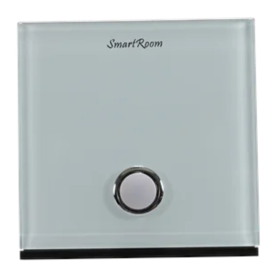
Function Illustration Multi-Functional Key System Indicator Light Status Indicator Light Push Button Push Button Decorative Cover Main Body Single Button Switch... - Page 7 Function Illustration Push Button Push Button Status Indicator Light Multi-Functional Key System Indicator Light Status Indicator Light Push Button Push Button Decorative Cover Main Body Two Buttons Switch...
- Page 8 Function Illustration System Indicator Light Push Button Push Button Multi-Functional Key Status Indicator Light Push Button Push Button Push Button Status Indicator Light Status Indicator Light Decorative Cover Main Body Three Buttons Switch...
-
Page 9: Installation Steps
Installation Steps 1. Connecting wire as the following picture: Single Live Line Switch Port Single Button Two Buttons Three Buttons One-way Load One-way Load One-way Load Live Line Output Live Line Output Live Line Output Two-way Load Two-way Load ∕ Live Line Output Live Line Output Three-way Load... - Page 10 Installation Steps Null and Live Line Switch Port Single Button Two Buttons One-way Load One-way Load Output Output Two-way Load ∕ Output Null Line Input Live Line Input Warning: Please confirm the electrical power source is off before installation. Electricity manipulation is dangerous.
- Page 11 Installation Steps 2. Press the Buckle Button and remove the Decorative Covers. Fix the product in the Wall Mount Base with two screws. Installation method is same to the standard wall switch. Decorative Cover Main Body Buckle Button Wall Mount Base...
- Page 12 Installation Steps 3. Attach the Decorative Cover. Installation is complete. (Please finish setting up the network before installation.)
-
Page 13: Networking Setting
Networking Setting 1. Please make sure the gateway(additional purchase) ZigBee network is working and this product has power within effective communication distance of gateway before setting. Attention: for more details please refer to wireless gateway instruction. Note: The guide is taking the three buttons switch as an example. - Page 14 Networking Setting 2. Press Multi-Functional Key 4 times to join ZigBee network. System Indicator Light stays flickering when searching network. Upon successful connection, System Indicator Light will stay lit in 2 seconds and then goes off. System Indicator Light goes off after staying lit in 2 seconds Press Multi-Functional Key 4 times quickly.
- Page 15 Networking Setting 3. Press Multi-Functional Key 10 seconds to restore to factory setting and exit ZigBee network. System Indicator Light goes off after flickering 4 times Press Multi-Functional Key 10 seconds...
- Page 16 Networking Setting 4. Press and hold the Multi-Functional Key, then quick click the Push Button which wanted to binding 3 times, sending the binding request. The Application Indicator Light will flashes 3 times if successful, flashes 6 times in 20 seconds if failed. Push Button Status Indicator Light Multi-Functional Key...
- Page 17 Usage 1. Each Push Button in the panel is linked with one corresponding switch. Pushing the button repeatedly allows changing the loaded condition. When the load condition is off, Status Indicator Light stays lit. Otherwise, Status Indicator Light goes off. 2.
-
Page 18: Product Standard
Product Standard Communication Way IEEE802.15.4(ZigBee) Communication Distance 100m( visible) Each resistive load 300W (filament lamp, spotlight) Single Live Line Each inductive and capacitive load,150W(energy saving lamp, fluorescent lamp, LED) Each resistive load 1500W(filament lamp.spotlight), 2000W in total Load Type Null and Live Line Each inductive and capacitive load1000W(energy saving lamp, fluorescent lamp, LED), 1500W in total Single Live Line... - Page 19 Product Standard Power Supply 110~240V Working Temperature -10℃~+45℃ Weight 250g Net Weight 200g Various materials and colors are offered Color...
-
Page 20: Ordering Information
Ordering Information Product Model Art.No. WL-SR-SF-01 SRPN1303101 Wireless One Button Single Live Line Switch WL-SR-SFD-01 SRPN1307101 Wireless One Button Single Live Line High-Power Switch WL-SR-SFG-01 SRPN1303111 Wireless One Button Single Live Line Switch (Tempering Glass) WL-SR-DF-01 Wireless Two Button Single Live Line Switch... - Page 21 Product Model Art.No. WL-SR-SND-01 SRPN1307501 Wireless One Button Null and Live Line Switch WL-SR-SNDG-01 SRPN1307511 Wireless One Button Null and Live Line Switch( Tempering Glass) WL-SR-DND-01 SRPN1307502 Wireless Two Buttons Null and Live Line Switch WL-SR-DNDG-01 SRPN1307512 Wireless Two Buttons Null and Live Line Switch( Tempering Glass) Package Size 130×110×50mm...
- Page 24 B14 Software Valley, NO.15, Fengji Avenue, Yuhuatai District, NanJing Service hotline :400-928-9288 www.wulian.cc/english/...
Need help?
Do you have a question about the WL-SR-SF-01 and is the answer not in the manual?
Questions and answers