Advertisement
Quick Links
Advertisement

Related Manuals for Inovus Medical Lapar Pro

Summary of Contents for Inovus Medical Lapar Pro
- Page 2 When opening your simulator it is recomended that you unpack all package contents and arrange them before starting construction. Once you have done this, take the first part labelled AR20_BTM01 and lay it on a secure flat surface. Now take the following parts: MA01 x2 AR20_U02 x1 WN14 x2 M5B24 x2. Using the image as a guide, pay close attention to the part orientation in this step or you will have to undo work at a later stage.
- Page 3 Take 4x AR20_M-BKT, position them in the keys provided. In a practical sense this will need to be done one at a time with the simulator positioned on its side. Using 4x M5B24 screw each AR20_M- BKT into position on the base. These parts are threaded for ease of assembly. 7 | At this stage the simulator should look exactly like the reference image. If something appears to be incorrect, go back through the steps again.
- Page 4 9 | Now attach 3x WN14 to the bolts coming through the bottom surface. Repeat this process on the opposite side to complete the assembly. 10 | Remove the AR20_CAM from its packaging and place into positon as shown. 11 | Take 2x M5B24 bolts and affix the AR20_ CAM into position. DO NOT plug-in at this stage. 12 | Take the sub-assembly from the last four steps and place it over the upright panels of the simulator as shown.
- Page 5 Locate following parts: MA01 x4 WN14 x4 M5B24 x4 Repeat the process from steps 2,3 & 4. Do this on each corner so that a magnet is in place for the side panels to connect into. It is important to note that the simulator is capable of multiple platform positions. When inserting AR20_TAB you will most commonly use the angled base for Augmented Reality applications.
- Page 6 17 | Connect the USB micro into the back of the camera. Start the assembly of your portable trolley system by unscrewing the M8 bolts at the rear of chassis so that you have around 3-4mm of space between the head of the bolt and the chassis wall. You can do this using the allen key provided. Take the L shaped screen bracket and place it onto the M8 bolts as shown. Drop the bracket onto the bolts. 20 | Screw the bolts tight using the allen key provided. Be careful not to overtighten at this...
- Page 7 21 | Take the assembled monitor bracket and clamp it in position as shown. 22 | Screw the clamp until tight. 23 | Attach the monitor screen using the 4x M4 bolts provided. 24 | As shown in the image, plug in the IEC, HDMI & USB cables.
- Page 8 25 | Carefully thread the 3 wires we plugged in during the previous step up through the L shaped bracket and onto the monitor bracket. Move to the next step. 26 | Position the wires as such and plug in to the appropriate socket. 27 | Plug the IEC connector into the back of the system. 28 | Plug the connector into the mains power.
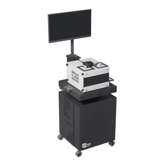
- Page 9 29 | If a WIFI connection isn’t present, plug in the network cable provided with the system. 30 | Place your constructed simulator that you should have already assembled onto the top surface. 31 | Plug in the USB cable to the USB ports on the trolley system (Note: depending on the system you have purchased, USB port location may vary).
-
Page 10: Warranty
Warranty This limited warranty applies to any order, purchase, receipt, delivery or use of any products and services (collectively, in a “purchase”) from Inovus Ltd or any of its subsidiaries or affiliates or authorised reseller (“reseller”). If you enter into a separate written agreement with any of the aforementioned this warranty may be declared null and void. - Page 11 Returns Policy Thank you for purchasing from Inovus. If you are not entirely satisfied with your product then there are few ways we can help: Returns You have 14 calendar days to return an item from the date you received it. To be eligible for a return, your item must be unused and in the same condition that you received it. Your item must be returned in the original packaging and you must have the receipt or proof of purchase. Responsibility for the product will remain with you until it is received by Inovus. Refunds/Replacements Once we receive your item, we will inspect it and notify you that we have received your returned item. We will immediately notify you on the status of your refund after inspecting the item.
- Page 12 Designed and manufactured by E: info@inovus.org T: +44 (0) 1744 752 952 W: www.inovus.org...
Need help?
Do you have a question about the Lapar Pro and is the answer not in the manual?
Questions and answers