Table of Contents
Advertisement
Quick Links
Shenzhen ZhongLing Technology Co.,Ltd.
Ad d : 8 th Fl oor, Buildi ng 3 , Qi yu Indu s tri al Ci ty, Gongl e
Ti ezai Rd ., Xi xi ang St., Bao' an Di s t, Sh en zh en, C hin a
Pos tc od e: 5181 02
Tel : +86- 0755 -2979 9 302
Fax: +8 6-07 55-2 912 428 3
E m ai l: s al es @zl ingk j.c om
Web: www.z ling kj .c om
ZLIM57
Integrated Open Loop Step Motor
Manual
【 P le a se r e ad t he m a nua l i n det a il b ef or e use, t o a v o i d da m a g e t o t he m ot or 】
(P UL S E C ON TR O L)
Advertisement
Table of Contents

Subscribe to Our Youtube Channel
Related Manuals for ZLTECH ZLIM57


Summary of Contents for ZLTECH ZLIM57
- Page 1 ZLIM57 Integrated Open Loop Step Motor Manual (P UL S E C ON TR O L) 【 P le a se r e ad t he m a nua l i n det a il b ef or e use, t o a v o i d da m a g e t o t he m ot or 】...
- Page 2 ZLIM57 Integrated Open Loop Step Motor Manual Version 1.01 ZLIM57 Integrated Open Loop Step Motor Manual Version 1.01 RELEASE NOTES: CONTENTS Version Update Time Update Content Updater PREFACE .......................3 V1.0 2018-10-12 First Version SAFETY PRECAUTIONS ..................3 1. PRODUCT INTRODUCTION ..................6 V1.01...
- Page 3 During installation, be sure to tighten the mounting screws of the PREFACE integrated step-servo motor. It should be protected from vibration and shock. Thanks for choosing ZLIM57, the open loop integrated stepper motor. This manual describes the installation, debugging, maintenance, operation and Wiring other aspects of the integrated step-servo motor ZLIS57.
- Page 4 Do not change the parameter settings of the integrated step-servo motor at will. The parameter modification needs to be performed under standby ZLIM57 is a 2 phase hybrid open loop stepper motor with high-performance digital condition. integrated driver. The system structure is simple and the integration is high. This series...
- Page 5 ZLIM57 Integrated Open Loop Step Motor Manual Version 1.01 ZLIM57 Integrated Open Loop Step Motor Manual Version 1.01 plotter, small engraving machine, CNC machine tool, pick and place device. It is particularly effective in applications where users expect low noise, low vibration, high stationarity and high precision.
- Page 6 ZLIM57 Integrated Open Loop Step Motor Manual Version 1.01 ZLIM57 Integrated Open Loop Step Motor Manual Version 1.01 Could be customized according to 3. DRIVER INTERFACE AND WIRING customer’s demand. 1 2 3 4 5 3.1.2 DIP switch Port Mark...
- Page 7 ZLIM57 Integrated Open Loop Step Motor Manual Version 1.01 ZLIM57 Integrated Open Loop Step Motor Manual Version 1.01 Fig.2 Control signal interface wiring diagram If input control signal single-ended, its control signal interface wiring diagram is shown Fig.4 Control signal timing diagram...
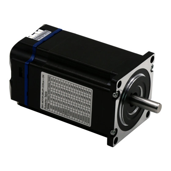
- Page 8 4. DIP SWITCH SETTING 4.2. Motor Rotation Direction Setting SW1=off, the motor rotates counterclockwise (CCW); ZLIM57 uses a five-digit dial switch, set the step resolution accuracy and motor rotate SW1=on, clockwise rotation (CW). direction. The detailed description is as follows:...
Need help?
Do you have a question about the ZLIM57 and is the answer not in the manual?
Questions and answers