Table of Contents
Advertisement
Quick Links
Advertisement
Table of Contents

Related Manuals for NOAH ACTUATION SA003 Series

Summary of Contents for NOAH ACTUATION SA003 Series
- Page 2 NOAH ACTUATION CO.,LTD. 1. Caution ELECTRICAL SHOCK HAZARD To avoid serious personal injury, property damage or death, turn off all power to the actuator before removing the cover. Before installation or use, verify the nameplate information to insure the correct model number, torque, voltage and enclosure type.
- Page 3 SERIES MANUAL 2. Storage The actuator must be stored in a clean, dry and temperature controlled area. The actuator shall be stored with the cover installed and with the conduit openings sealed. Storage must be off the floor. Care must be taken to guard the actuator from condensation during extreme temperature variation.
-
Page 4: Standard Specification
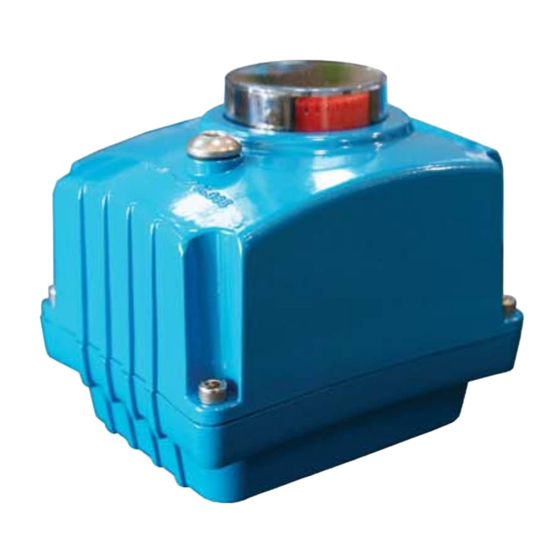
NOAH ACTUATION CO.,LTD. 4. Standard Specification Enclosure Weatherproof Enclosure IP67 Nema 4 and 6 Ambient Temperature -20℃ to +70℃ DC24V, AC24V Power Supply AC110 / 230V 50/60Hz Limit Switches Open / Close + Dry Contact Open / Close (250AC 5A) Travel Angle 0˚~ 90˚... - Page 5 SERIES MANUAL 6. Exterior Parts Identification Window Manual Sealing Bolt Top Cover Top Cover Bolts Body Earth Base L-Wrench Cable entries Emico Noah...
- Page 6 NOAH ACTUATION CO.,LTD. 7. Interior Parts Identification Auxilliary Open Limit Switch Open Limit Switch Auxilliary Close Limit Switch Close Limit Switch Indicator Heater (2EA) Control Board Full Open / Close LED Lamp Motor Terminal Micro Switch Earth Emico Noah...
-
Page 7: Actuator Installation
SERIES MANUAL 8. Actuator Mounting Flange SA003 Base is manufactured to the ISO 5211 standard. If the actuator does not fit directly to the valve, drive inserts are available or complete mounting kits can be supplied as request. 11 DP20 Mounting Base B.C.D ISO 5211 F03(Φ36 M5TAP DP8) ISO 5211 F04(Φ42 M5TAP DP10) -
Page 8: Manual Operation
NOAH ACTUATION CO.,LTD. 10. Manual Operation 10-1 Remove the manual sealing bolt using the wrench attached on the bottom of the actuator. 10-2 Turn the wrench to the clock wise for opening and count clock wiser for closing inserting the wrench. -
Page 9: Wire Connection
SERIES MANUAL 12. Indicator Setting The position of the valve is indicated by the visual dome indicator. Window Indicator Bolt LED lights illuminate to allow for easy visual confirmation of full close and full open ※ If the position of the indicator is not aligned correctly, an adjustment can be made by simply loosening the bolt and manually turning the indicator to the proper location, then re-tightening the bolt 13. -
Page 10: Electric Wiring
NOAH ACTUATION CO.,LTD. 14. Electric Wiring actuator 14-1 Remove the cover by loosening the four captive cover bolts. 14-2 actuator Confirm that the wiring diagram located in the and the wiring number on the nameplate match correctly. 14-3 actuator Confirm that the main power and supply described on the nameplate of the match correctly. -
Page 11: Maintenance
SERIES MANUAL 15. Maintenance It is recommended that the actuator be cycled every two weeks after purchase. To minimize the effects of condensation in the actuator, conduit entries should be sealed properly and the heaters should be energized regularly. 16. Warranty Void Information 16-1 Failure or damage caused by misuse or abuse. - Page 12 NOAH ACTUATION CO.,LTD. 18. Wiring CLS : Close Limit Switch (250VAC 3A) OLS : Open Limit Switch (250VAC 3A) ACLS : Aux Close Limit Switch (250VAC 3A) AOLS : Aux Open Limit Switch (250VAC 3A) 19. Dimension SA003 BASE 11 DP20 Cable Entries 2-PF1/2”...
Need help?
Do you have a question about the SA003 Series and is the answer not in the manual?
Questions and answers