Table of Contents
Advertisement
Quick Links
Advertisement
Table of Contents

Subscribe to Our Youtube Channel
Related Manuals for CSQ VL10 Series

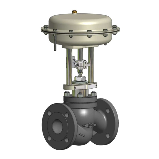
Summary of Contents for CSQ VL10 Series
- Page 2 1.0 INFORMACIÓN DE SEGURIDAD 1.0 SAFETY INFORMATIONS El uso seguro de este producto se garantiza únicamente The safe operation of this product is guaranteed only if cuando está instalado, puesto en servicio, en uso y en installed, put in service, used and maintained in mantenimiento por una persona con conocimientos de las appropriated way by skilled people in conformity to the instrucciones de operación.
-
Page 3: Instalación
1.08 SISTEMAS BAJO PRESIÓN 1.08 PRESSURE SYSTEMS Asegúrese de que la presión ha sido aislada y de todos los Ensure that any pressure is isolated and safety vented to sistemas de vento a presión atmosférica. Considere una atmospheric pressure. Consider double isolation (double doble isolación, y de que las válvulas de corte sean block and bleed) and the locking or labelling of closed bloqueadas y etiquetadas. - Page 4 2 INSTALACIÓN 2 INSTALLATION Para permitir un mantenimiento periodico, en caso de una To allow the periodical maintenance in case of continuos operación continua de la planta, la linea debe contar con operation plant, provide as required, manual block valves válvulas de corte (Fig.
-
Page 5: Mantenimiento
4.01 AJUSTE DEL RECORRIDO DESDE DN15 A DN100 4.01 ADJUSTMENT OF THE VALVE TRAVEL (1"- 4") FROM DN15÷DN100 (1"÷4") Según Fig. 2, proceda de la siguiente manera: In reference to the Fig. 2, proceed as follows: - Vacie el actuador de aire y párelo a un tercio de su - Release air supply to the actuator and stop it at one third carrera aproximadamente. - Page 6 5.01 SUSTITUCIÓN DE LA MEMBRANA 5.01 REPLACEMENT OF ACTUATOR DIAPHRAGM Según figura 6 y 8, para actuadores de acción inversa y In reference to the figure 6 and 8 for reverse action figuras 5 y 7 para actuadores con acción directa, siga los actuators and the figure 5 and 7 for direct action actuators, siguientes procedimientos: proceed as follow:...
- Page 7 5.02 SUBSTITUCIÓN DEL DISCO PISTÓN EN 5.02 REPLACEMENT OF ON/OFF PISTON DISC ACTUADORES NEUMÁTICOS TIPO PISTÓN ON/OFF VALVE Según figura 9, para actuadores de acción inversa y figura In reference to the figure 9 for reverse action actuators 10, para actuadores con acción directa, siga los siguientes and the figure 10 for direct action actuators, proceed as procedimientos: follow:...
- Page 8 5.03 DESMONTAJE DEL ACTUADOR EN VÁLVULAS DE 5.03 REMOVING ACTUATOR FROM VALVE DN15 A DN100 (1"- 4") FROM DN15÷DN100 (1"÷4") Según la figura 11, siga el siguiente procedimiento: In reference to the figure 11, proceed as follows: - Remueva los tornillos (1) y el acoplamiento (2). - Remove the screws (1) and the clamp (2) - Desenrosque la arandela completamente (3).
- Page 9 5.04 DESMONTAJE DEL ACTUADOR EN VÁLVULAS DE 5.04 REMOVING ACTUATOR FROM VALVE DN125 A DN200 (6"- 8") FROM DN125÷DN200 (6"÷8") Según figura 13, proceda de la siguiente manera: In reference to the figure 13 proceed as follow: - Desenrosque la tuerca (1). - Screw off the lock nuts (1).
- Page 10 5.05 SUBSTITUCIÓN DEL OBTURADOR 5.05 REPLACING PLUG Siga el procedimiento anterior por tal de desmontar el Separate the actuator from the valve body as described on actuador. Según figura 15, proceda de la siguiente manera: the above paragraphs. In reference to the figure 15 - Extraiga la pieza roscada (1) y desenrosque las tuercas proceed as follow: (2).
- Page 11 5.06 OBTURADOR BALANCEADO 5.06 PRESSURE BALANCED PLUG Separe el actuador del cuerpo de la válvula como descrito Remove the actuator from the valve body as described on anteriormente. Según figura siga siguiente the previous paragraphs. In reference to the figure 16 procedimiento: proceed as follows: - Extraiga la pieza roscada (1) y desenrosque las tuercas...
- Page 12 5.07 VÁLVULA CON FUELLE DE SEGURIDAD 5.07 VALVE WITH SAFETY BELLOWS Separe el actuador del cuerpo de la válvula como descrito Separate the actuator from the valve body as described on anteriormente. Según figura siga siguiente the above paragraphs. In reference to the figure 17 procedimiento: proceed as follow: - Afloje las tuercas (2) y retírelas.
-
Page 13: Replacing Packing
5.08 SUSTITUCIÓN DE LA ESTOPADA 5.08 REPLACING PACKING Desmonte el obturador completo según los descrito en el Take off the complete plug stem as described on previous anterior párrafo. Según Figuras 20,21,22 y 23, siga el paragraphs then, in reference to the figure 20, 21,22, and siguiente procedimiento: 23 proceed as follow: - Desmonte la pieza roscada (1) - Page 14 5.09 MANTENIMIENTO PERIÓDICO 5.09 PERIODICAL CHECKING Después de 24 horas desde la primera operación, revise After 24 hours from the first operation, check the piping las conexiones a las tuberías y verifique el correcto apriete connections and verify the tightening of flanges locknuts. de las tuercas de las bridas.
Need help?
Do you have a question about the VL10 Series and is the answer not in the manual?
Questions and answers