Table of Contents
Advertisement
Quick Links
Advertisement
Table of Contents

Related Manuals for Oxygen 8 VITA HRV

Summary of Contents for Oxygen 8 VITA HRV
- Page 1 INSTALLATION & OPERATION MANUAL VITA HRV...
-
Page 3: Table Of Contents
Table of Contents 1.0 Safety Instructions 2.0 Components 2.1 Polypropylene Core 3.0 Wiring Diagrams 3.1 Control Board 3.2 Vita 120 ECM 3.3 Furnace / Fan Coil / Heat Pump Interlock 4.0 HRV Typical Installations 4.1 Typical Installations for a House 4.2 Installation Options for a High-Rise Condominium 4.3 Horizontal and Vertical Installations 4.4 Typical Installations of Single Vents and Access Door... -
Page 4: Safety Instructions
Installation Manual Vita Series 1.0 Safety Instructions READ AND SAVE THESE INSTRUCTIONS Caution Warning Turn the unit OFF during construction or repair to avoid To reduce the risk of fire, electric shock or injury, observe filter blockage. the following: Exhaust air outside - Do not intake/exhaust air into Read all instructions carefully before installations, spaces within walls, crawl spaces, garage or into attics. -
Page 5: Components
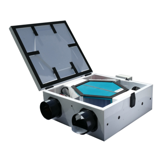
Installation Manual Vita Series 2.0 Components 2.1 Vita 120 Polypropylene Core Reference Description Part Number RERV-C100 NF Qty. HRV - lid, Pan Assembly 9315 Polypropylene Collar 5" Dia. 014043C Counterflow Plastic Core CF100 Filter 7" x 12" (MERV-4) 9358 Temperature Sensor 9326 5"... -
Page 6: Wiring Diagrams
Installation Manual Vita Series 3.0 Wiring Diagrams 3.1 Control Board Recently we modified our control board layout to provide easy wiring connections for timer switches/intermittent switches (low voltage) without accessing the electrical box. Initially, some units may come with different versions of the control board. Optional Accessories (Not Supplied) a. -
Page 7: Vita 120 Ecm
Installation Manual Vita Series 3.2 Wiring Diagram: Vita 120 ECM Control Board Control Board Low Voltage Side Connections High Voltage Harnesses & HRV AC Power Input Max Current: 5A 120 VAC Light/Switch Options... -
Page 8: Furnace / Fan Coil / Heat Pump Interlock
Installation Manual Vita Series 3.3 Wiring Diagram: Furnace / Fan Coil / Heat Pump Interlock Warning: Never connect a 120V AC circuit to the terminals of the furnace/fan-coil/heat pump interlock (Standard Wiring). Only use the low voltage class 2 circuit. Standard Interlock Wiring For a furnace connected to a cooling system On some older thermostats, energizing the R and G terminals at the furnace has the effect of energizing Y at the thermostat and... -
Page 9: Hrv Typical Installations
Installation Manual Vita Series 4.0 HRV Typical Installations 4.1 Typical Installations for a House Fully Ducted System This is a standalone HRV system which is not connected to a forced air system. Stale air is drawn from key areas of the home (bathroom, kitchen) while fresh air is supplied to main living areas. -
Page 10: Installation Options For A High-Rise Condominium
Installation Manual Vita Series 4.2 Installation Options for a High-Rise Condominium Fully Ducted System With Fan Coil System Fresh air from outside should be installed on the Fan-Coil supply side (HRV station #2) and the HRV should be interlocked with the Fan-Coil unit. Note All exhaust fans must be installed minimum of 5 ft. -
Page 11: Horizontal And Vertical Installations
Installation Manual Vita Series 4.3 Horizontal and Vertical Installations 32" clearance is recommended for cleaning of the core and servicing the unit (use appropriate door size). Dampers are installed for horizontal installation. For vertical installation, both dampers must be turned so they can open and close properly when there is any backdraft. -
Page 12: Typical Installations Of Single Vents And Access Door
Installation Manual Vita Series 4.4 Typical Installations of Single Vents and Access Door Intake Exhaust Notes Fresh air intake and supply duct must be totally insulated. The Exhaust duct must be 5' insulated from the wall. In colder climates, it is recommended to insulate all exhaust and supply ducts. Check building codes for insulation requirements. -
Page 13: Drain Connection
Installation Manual Vita Series 4.5 Drain Connection During the defrost cycle, the HRV unit may produce some condensation and the water should flow into a nearby drain. The HRV cabinet has pre-punched holes (two on the side and one on the door) for the drain, in order to keep the drain pan intact, hand tighten the plastic drain spout to the unit using the gasket and nuts. -
Page 14: Airflow Balancing
Installation Manual Vita Series 5.0 Air Flow Balancing 5.1 Balancing Procedure It is required to have balanced airflows in an HRV. The volume of air brought in from the outside must equal the volume of air exhausted by the unit while running at a normal speed. If the airflows are not properly balanced, then: The HRV may not function at its maximum efficiency. -
Page 15: Airflow Balancing In Duct
Installation Manual Vita Series 5.3 Airflow Balancing in Duct Note (Option 2): Duct Diam. Cross Sect. Area ∆P" For balancing, the extension box cover plate is provided 5" 0.136 sq. ft. 5" 6" with 3 holes on the supply side and 3 holes on the exhaust 6"... -
Page 16: Maintenance
Installation Manual Vita Series 6.0 Maintenance 6.1 Regular Maintenance Turn off the unit and disconnect the power supply. Attention Unlatch the door and lift the door panel towards you, hold it firmly and slide it to the left. Do not use a cleaning solution Clean the inside of the door and drain pan with a damp cloth to remove dirt and debris for the HRV core that may be present. -
Page 17: Troubleshooting
Installation Manual Vita Series 7.0 Troubleshooting Problems Possible Causes Solution Airflow is too low HRV airflow is improperly balanced (for units Have professional balancer or contractor without built-in Automatic Electronic Air balance the unit Balancing) Remove and clean filter Filter clogged Remove and clean core Core Obstructed Remove and clean the blockage... - Page 18 Installation Manual Vita Series 10. LEDs on the Main Control Board and Damper obstructed Check back-draft damper, no screw must the remote wall Timer Switch flashes Supply fan jam interfere with the function of the damper 0.5 seconds On / 0.5 seconds Off / Replace the fan 0.5 seconds On / 0.5 seconds Off / 0.5 seconds On / 0.5 seconds Off /...
Need help?
Do you have a question about the VITA HRV and is the answer not in the manual?
Questions and answers