
Related Manuals for TIANJIN BAILI ERTONG MACHINERY SMC Series


Summary of Contents for TIANJIN BAILI ERTONG MACHINERY SMC Series
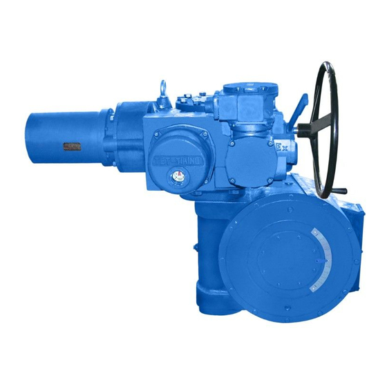
- Page 1 SM-20 (Read this operation manual carefully before using the product) SMC Series Valve Electric Actuator Operation Manual TIANJIN BAILI ERTONG MACHINERY CO., LTD.
- Page 2 Content Part I SMC Series Basic Type Operation Manual ..........1 Part II SMC series integral type operation manual ..........13 Part III SMC explosion-proof type operation manual ......... 14 Part IV SMC-04~SMC-2 low-temperature operation manual ......16 ...
-
Page 3: Part Ismc Series Basic Type Operation Manual
SMC series could be electrically remotely controlled (in the control room) and could also controlled by control buttons on site so as to be operated locally. SMC series’ manual operation mechanism realize local manual operation against valve. - Page 4 worm and worm gear and various motor gears and worm shaft gears combination, so that can get wider output speed range.
- Page 5 4.3 Driving tubular shaft: it is the electric actuator’s power take-off component, including three types which are 2-PC, 1-PC and jaw type. For its structure, refer to Fig.10 to Fig.12. 2-PC driving tubular shaft has a inside valve stem nut and electric actuator bears valve’s axial force. Generally, valve stem’s inner thread is processed by user.
- Page 6 The stroke control movement of SMC-04~2 starts from low-speed shaft(driving tubular shaft). The limit control movement of SMC-3~5 starts from high-speed shaft(worm gear shaft). Limit control mechanism of SMC series is also called “gear limit switch” (herein after referred as G·L·SW).
- Page 7 For its structure, refer to Fig.16. It can provide two kinds of contact types which are 4R-2C and 4R-4C. 4R-2C type has 8 self-cleaning, large capacity, swiveling contact switches. 4R-4C has 16 this kind of switches. According to control modes, it shall be chose by user when places orders. Each row of the swiveling contact on the G·L·SW’s position could be arranged freely.
- Page 8 4.8 Position indicator mechanism: it is used to show valve’s position. It is also called MDPI. Two functions: pointer-dial scale type, indicating valve position on site; potentiometer makes feedback of valve position to show in the control room. The above functions could be totally or partly provided to user.
- Page 9 5. Mounting and dismantling(against the valve) 5.1 Beforehand, process the valve stem nut’s inner thread or spline jointed head’s inner hole/ key, so that will fit with the valve(1-PC and jaw type driving tubular shaft do not need to do so.) 5.2 Mounting and dismantling methods for the electric actuator with 2-PC driving tubular shaft are as following: Put the processed valve stem nut in the tubular shaft and fix it by using locknut.
- Page 10 7. Electric control principle diagram and electric wiring. Because the electric control principle of SMC series electric actuators are in wide range, the electric control principle diagram which used in practice behind the instruction as an attachment. The terminal contrast table, electric element data table are on the Basic electric control principle diagram.
- Page 11 8.1 Close position adjusting of valve (adjustment of rotor of “row 4”). Ensure the phase sequence of power source is identical with the direction “open” and “close” of the valve before adjusting. If it is not clear whether the phase sequence is right, according to the above 7.5. Be sure to cut off the power before adjustment.
- Page 12 used for adjusting. (Note: Screw out the “adjusting screw” NO.5 after adjustment stroke of the actuator and inspect it.) 8.3 Accurate adjusting If the valve switch position is not reached after the initial adjusting, accurate adjusting should be carried out. Following is the procedure of “close direction”...
- Page 13 “100%” position and the valve open indicator lamp is lighted up. The pointer of the position indicator on the controller should be in corresponding position when it is in “ON” “OFF” position. If not, it can be adjusted by the potentiometer that located on controller. 10.
- Page 14 11.14The design service life of actuator is 8000 times. 11.15 According to the regulations on the recycling and treatment of waste electrical and electronic products, please comply with the relevant national regulations and properly dispose of waste products. Or call our after-sales service department for recycling.
-
Page 15: Part Ii Smc Series Integral Type Operation Manual
SMC Standard(explosion-proof)type so that it is convenient for the user to operate or to debug. 2. Function and features SMC series Integral type of electric actuator has provided several of electric control means and functions. Users make his choice according to their needs. Major functions and features: 2.1 Automatic phase-discriminator; phase-loss protection 2.2 DC24V is applied for remote control;... -
Page 16: Part Iii Smc Explosion-Proof Type Operation Manual
SMC series have achieved Conformity Certificate of Explosion-Proof issued by the above organization.(Pay attention to the nameplate which includes the product’s technical conditions serial No. and the Certificate of Explosion-proof No.). - Page 17 diagram(attached in the manual operation) to suit for three types mentioned in the Summary. User can identify its kinds according to the nameplate. In the standard schematic diagram, D1, D2, D3 and N are aligned with U,V,W,E on the terminal board(that is, D1→U,D2→V,D3→W,E→N).
-
Page 18: Part Iv Smc-04~Smc-2 Low-Temperature Operation Manual
Part IV SMC-04~SMC-2 low-temperature operation manual 1. Summary This part is the instruction for SMC-04~SMC-2(including the Explosion-proof type, Integral explosion-proof type and combined quarter-turn type) low temperature type of electric actuator. When low temperature type is applied, for mounting and debugging, refer to the manual operation of standard type of electric actuator;... - Page 19 And reassembled, the user should ensure that the sealing is not affected with disadvantage. Tianjin Baili Ertong Machinery Co., Ltd. Address: Block B,No.180 Hanghai Road, Tianjin Pilot Free Trade Zone (Airport Economic Zone)
Need help?
Do you have a question about the SMC Series and is the answer not in the manual?
Questions and answers