Table of Contents
Advertisement
Quick Links
(Please read this Operation Manual carefully before using this product.)
SM-20
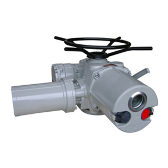
IMT Series Intelligent Multi-turn Electric Valve Actuator
IMT Explosion-proof Series Intelligent Multi-turn Electric Valve
Actuator
Operation Manual
Tianjin Baili Ertong Machinery Co.,Ltd
(Former Tianjin No.2 General Machinery Plant)
Advertisement
Table of Contents

Related Manuals for TIANJIN BAILI ERTONG MACHINERY IMT Series


Summary of Contents for TIANJIN BAILI ERTONG MACHINERY IMT Series
- Page 1 (Please read this Operation Manual carefully before using this product.) SM-20 IMT Series Intelligent Multi-turn Electric Valve Actuator IMT Explosion-proof Series Intelligent Multi-turn Electric Valve Actuator Operation Manual Tianjin Baili Ertong Machinery Co.,Ltd (Former Tianjin No.2 General Machinery Plant)
-
Page 2: Table Of Contents
Contents Part I Machinery configuration and mounting…………………………………1 1. Summary 2. Major features 3. Main structure 4. Connection with valve 5. Lubrication 6. Electric wiring 7. Notice Part II Set up and adjustment………………………………………………..…4 1. Local control 2. Operation instruction for actuator: 3. -
Page 3: Part I Machinery Configuration And Mounting
3.6 Torque control mechanism: it controls output torque and protects electric actuator from over-loading and being jammed. The working schematic for IMT series output torque: axial force from worm gear acts on Belleville spring, and it drives torque switch to finish torque control. User is forbidden to adjust the torque value which is locked and required by user before factory delivery. -
Page 4: Connection With Valve
signal. It is composed of middle transmission mechanism, absolute encoder, integrated circuit board, and etc... It records and processes the rotation turns of output shaft to have valve controlled. Use selector switch and remote setter to set up actuator after it has been connected with valve, so that a precise limit position and required valve position feedback are acquired. -
Page 5: Electric Wiring
before dispatch. User shall inject oil before operation. 6. Electric wiring 6.1 Confirm that power supply voltage is identical with that of the actuator. 6.2 Wiring procedure and ways: 6.2.1 Open wiring case, remove sealing tools for inlet wire. 6.2.2 Ways of cable inlet 1. -
Page 6: Part Ii Setup And Adjustment
Part II Setup and adjustment 1.Local control: Local control and parameter setup for IMT intelligent electric actuator can be made through local buttons and remote setter. Note: While using remote setter, status selector switch shall be turned at “Local”, and operating selector switch shall be turned at “Stop”. If not, electric actuator would shows “Wrong Setup”... -
Page 7: Adjustment For Electric Actuator
After powering up and initialization, valve position in big size font is displayed on the whole LCD. At fully-open position and fully closed position, valve position of butterfly valve is shown in the following pictures. At Rest Closing Basic Settings Enter? At Rest 56.1% Feedback Set... -
Page 8: Function Of Electric Acutuator And Parameter Setup
system will go back to the previous menu. 3.3.2 Set up limit position by local selector switch ① Turn status selector switch at “Stop”,turn operate selector switch at “Open” in three seconds, then goes into main menu. ② Turn the status selector switch from “Stop”→ “Local”, going into “Basic Settings”. After choosing “Accept Valve Close Limit”,on the right side there is the timely-position’s encoder(0~65535). - Page 9 4.1.7 Resume Default: While user needs to reset this item, this item can be used to reset factory setting, except for “Accept Valve close Limit”、“Accept Valve open Limit” and “The Valve Close Direction”. 4.2 Feedback set Adjust 4mA For CPF XX.XXmA Adjust 20mA For CPF XX.XXmA...
- Page 10 After choosing “Advanced Settings” and pressing “Ok”, input initial password “25” and go into the next menu. 4.3.1 ESD Control:When it is set “Disable”, ESD control is forbidden. When it is set “Enable”, “ESD” control is permitted,and go into next menu to setup(a~g). Factory setting:Disable. a.
- Page 11 under remote control. Choose “Disable” or “Open First” or “Close First”, and connect wires according to required ways. Factory setting: Disable. 4.3.8 Calibrate 4mA For ACC.: if 4mA control current sent by user is different from calibration value of the actuator, user can use this item to re-calibrate.
-
Page 12: Alarm Information
selector switch”. User can use this item to check the position of status selector switch. Note: In this item, using status selector switch to “get back” does not work. 4.4.2 Position Of The Operator Knob: after choosing this item, on the right side there will be the position of “Operator Knob”. -
Page 13: Referenced Control Wire Connection
will stop working. 5.9When alarm area displays “Motor Overload”, and actuator starts to function in open direction at fully closed position, if in 9-12s, valve position cannot be detected and this alarm is displayed, the actuator will stop working. This alarm means that maybe valve is jammed or actuator’s torque is not applicable with valve. 6.Referenced control wire connection(For example, IMT-01. -
Page 14: Part Iii Additional Instruction For Imt-04~4Ex Explosion-Proof Product
Part III Additional Instruction for IMT-04~4Ex Explosion-proof product 1. Summary IMT-04~4Ex explosion-proof intelligent product is produced on the basis of GB3836.1《General Requirement for the Equipment Used in Explosive Environment, Part I》and GB3836.2 《The Equipment Protected by Explosion-proof Enclosure “d” Used in Explosive Environment, Part II》. Meanwhile, this series have been tested, experimented and finally verified by the national verified explosion-proof organization and get Conformity Certificate of Explosion-Proof. - Page 15 Explosion-proof structure sketch map for IMT-04~03Ex Explosion-proof structure sketch map for IMT-00~2Ex Explosion-proof structure sketch map for IMT-3~4Ex Explosion-proof components table Item Quantity No. Item Quantity No. Item Quantity 1 Body case 6 Torque switch box 11 Openness window 2 Input shaft 7 Torque switch shaft 12 Wiring box 3 Gear frame cover...
- Page 16 Tianjin Baili Ertong Machinery Co., Ltd Add: Block B,No.180 Hanghai Road, Tianjin Pilot Free Trade Zone (Airport Economic Zone)
Need help?
Do you have a question about the IMT Series and is the answer not in the manual?
Questions and answers