Table of Contents
Advertisement
Quick Links
Advertisement
Table of Contents

Related Manuals for DRTECH EXT 1824G


Summary of Contents for DRTECH EXT 1824G
-
Page 2: To Customers
Disclaimer 1. In no event shall DRTECH be liable for any damage or loss arising from fire, earthquake, any action or accident by a third party, any intentional negligent action by users, any trial usage, or other usage under abnormal conditions. -
Page 3: Table Of Contents
Contents EXT 1824G User’s Manual Contents To Customers................................. 2 Contents.................................. 3 Safety notices ................................ 6 1. Safety Information ....................7 Safety precautions ......................7 1.1. Notes for using the equipment ..................12 1.2. 2. Introduction ......................15 Features..........................15 2.1. System Configuration....................... 16 2.2. - Page 4 Contents EXT 1824G User’s Manual WIFI & Bluetooth Workflow..........................29 4.3.3. Radio Frequency TX Power ..........오류! 책갈피가 정의되어 있지 않습니다. 4.3.4. 5. Operating Procedure.................... 30 Preparing to Use the Detector..................31 5.1. Standard Configuration ........................... 31 5.1.1. Battery Pack................................32 5.1.2.
- Page 5 Battery Pack or Installation Part of Battery is Getting Hot ........61 8.3. 9. Maintenance and Inspection................62 10. Specification......................63 Main Specifications......................63 10.1. EXT 1824G Detector ............................63 10.1.1. Battery Charger System..........................64 10.1.2. Battery Pack ..............................65 10.1.3.
-
Page 6: Safety Notices
Conventions EXT 1824G User’s Manual Safety notices The following safety notices are used to emphasize certain safety instructions. Follow the safety instructions in this user’s manual along with warning and cautions symbols. Ignoring such warnings or cautions while handling the product may results in serious injury or accient. -
Page 7: Safety Information
1. Safety Information EXT 1824G User’s Manual 1. Safety Information 1.1. Safety precautions Follow these saftey guides and properly use the equipment to prevent injury and damage to any equipment/data. WARNING Installation and environment of use - Do not use or store the equipment near flammable chemical such as alcohol, thinner, benzine, etc. - Page 8 EXT 1824G User’s Manual WARNING Handling The system, in whole or in parts, cannot be modified in any ways without any written approval from DRTECH. - No modification of this equipment is allowed - Never disassemble or modify the equipment.
- Page 9 WARNING Battery pack and charger - Do not use the battery pack as a power source for equipment other than EXT 1824G detectors. Be sure to use only the dedicated battery pack for the EXT 1824G detector. - The battery charger is designed for the dedicated battery pack. Do not use the battery charger other than the dedicated one.
- Page 10 1. Safety Information EXT 1824G User’s Manual WARNING Installation and environment of use - Do not install the equipment in any of the locations listed below. Doing so may result in malfuction, equipment faillng, fire or injury. ㆍ Close to facilities where water is used.
- Page 11 1. Safety Information EXT 1824G User’s Manual CAUTION Handling the equipment The Equipment must be handled with care to avoid personal injury or damage to the internal image sensor. - Handle the equipment carefully. - Do not submerge the equipment in water.
-
Page 12: Notes For Using The Equipment
• Run Ecali1 software after installing the system, at least once a year. If an error occurs, report the detailed error information to DRTECH local dealer or distributor. The owner is responsible for ensuring that the system diagnostic is CAUTION performed every year. - Page 13 User Limitation • The Ecali1 software has the technician mode which could only be operated by inputting the correct PASSWORD. The technician mode should be operated by the personnel who are qualified by DRTECH. Electric Shock Hazards • To reduce electric shock hazards, the system must be connected to an electrical ground.
- Page 14 The equipment must be handled with care to avoid personel injury or damage to the internal image sensor. • The EXT 1824G Wireless is an advanced wireless digital radiographic equipment in the DRTECH Extream series. This equipment is designed to provide the highest resolution and sensitivity in the series. In addition, the wireless LAN (IEEE 802.11n*) communication feature improves the operability, and high-speed processing.
-
Page 15: Introduction
Intended Use The EXT 1824G of Flat Panel Digital X-ray detector for industry was designed for industrial use. Intended conditions of use... -
Page 16: System Configuration
2. Introduction EXT 1824G User’s Manual 2.2. System Configuration Basic Configuration 2.2.1. Generally, the EXT 1824G detector is used in system configuration as illustrated below: Figure 2.1 EXT 1824G System Configuration EXT 1824G-UM-COM-EN-03... - Page 17 The time for charging and replacing the battery pack can be reduced drastically. EXT 1824G Wireless system consists of detector, CDs and relevant accessories. (Refer to chapter 3-1 “Product Components” for CD information) Table 2.1. EXT 1824G Packaging: Default components...
- Page 18 X-ray Detector (EXT 1824G) (EVS-BCS) (EVS-MBP-Y) Power adaptor (12V, 7.08A) User’s Manual CD(Software / Calibration) + AC Power Cable(2m) Table 2.2. EXT 1824G Packaging: Optional components DATA(LAN) Cable NDT Tether Cable(0.45M) EVS_Functional_Cable(5M) Option -. 1M -. 10M -. 25M -.100M...
-
Page 19: Product Description
Supported in all Modes WARNING The use of accessories and cables other than those specified, with the exception of EXT 1824G Wireless accessories and cables sold by DRTECH Co., LTD. as replacement parts for internal components, may result in increased emissions or decreased immunity of the equipment. Accessory equipment connected to the analog and digital interfaces must be certified according to the respective IEC standards. -
Page 20: S/W Trigger Mode
3.1.2. S/W Trigger Mode Table 3.2. Product componets for S/W Trigger Mode Part name Remark Flat panel detector EXT 1824G(Scintillator : Gadox) 1.7 kg Battery charger EVS-BCS : 0.5 kg Battery pack EVS-MBP-Y : 0.24 kg Document : User ‘s Manual (PDF) -
Page 21: Workstation (Recommended And Minimum But Not Included)
3. Production Description EXT 1824G User’s Manual 3.1.3. Workstation (Recommended and minimum but NOT included) Table 3.4. Workstation Item Specification Operating system Windows 7 64 bit SP1 (Professional Edition or higher) Intel Core i7 or higher (or compatible CPU) Memory... -
Page 22: Parts Name And Functions
Image Acquisition and Transfer Time < 4sec (with HR Mode) , < 3 sec (with HT Mode) Powered by the battery pack Rated Power Supply (DRTECH Corporation(Powerlinx) / EVS-MBP-Y /7.4V, 4000mAh) Wireless Powered by Power adaptor using tether interface Wired (XP Power / AHM85PS12 / DC12V 7.08A) -
Page 23: Detector Component
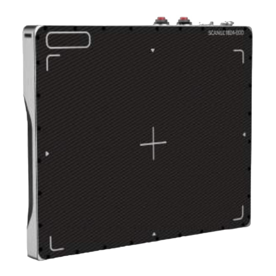
4.1.2. Detector Component The detector is designed to capture radiographic images. Captured images are transmitted to the EXT 1824G image-capture computer using the wireless/wired data transfer Figure 4.1. Detector Components A. Wireless antenna: Transmits image data with wireless comunication (IEEE802.11n). -
Page 24: Battery Charger And Battery Pack
4. Detector Component EXT 1824G User’s Manual 4.2. Battery Charger and Battery Pack 4.2.1. Battery Charger 4.2.1.1. Battery Charger Specifications Table 4.2. Battery Charger Specifications Item Description Model EVS-BCS Simultaneous Charging Battery Pack 2 EA Charging Time 3 hours Rated Power Supply DC +12 V, 6 A Max. -
Page 25: Battery Pack
4. Detector Component EXT 1824G User’s Manual 4.2.2. Battery Pack 4.2.2.1. Battery Pack Specification Table 4.3. Battery Charger Specifications Item Description EVS-MBP-Y Model Cell Type Lithium Polymer Number of Cells 2S1P (2series 1 Parallel) Rated Power Supply Output : DC +7.4 V Lifetime Approx. -
Page 26: Charging Battery Pack
4. Detector Component EXT 1824G User’s Manual 4.2.2.3. Charging Battery Pack The battery pack supplies power to the detector during wireless connection. Be sure to use only the dedicated battery pack, and fully charge it before usage. • Connect the power adapter to the DC Input port of the battery charger. The power LED lights in blue indicates the presence of direct current (DC) power. -
Page 27: Adaptor
4. Detector Component EXT 1824G User’s Manual 4.2.3. Adaptor Table 4.5. AD/DC Adaptor Specifications Item Description Model AHM85PS12 Rated input 100- 240Vac / 1.0A, 50/60Hz Rated output 12V, 7.08A Maker XP POWER EXT 1824G-UM-COM-EN-03... -
Page 28: Interface
4. Detector Component EXT 1824G User’s Manual 4.3. Interface 4.3.1. WIFI Specification Table 4.3. WIFI Specifications Item Wireless Module Standard IEEE 802.11abgn (2T2R) Data Rate 802.11b: 11Mbps / 802.11a/g: 54Mbps / 802.11n: 300Mbps IEEE 802.11abgn ISM Band, 2.400GHz ~ 2.4835GHz, Operating Frequency 5.150MHz ~ 5.825MHz... -
Page 29: Bluetooth Specification
4. Detector Component EXT 1824G User’s Manual 4.3.2. Bluetooth Specification Item Bluetooth Module Standard Bluetooth 4.1 Data Rate 1 Mbps Operating Frequency 2.4 ~ 2.48 GHz Interface UART, PIO, AIO, SPI Antenna Modulation GFSK Depends on profiles, Power Consumption: 12 mA typical... -
Page 30: Operating Procedure
4. Detector Component EXT 1824G User’s Manual 5. Operating Procedure General Workflow The following workflow indicates the procedures after startup of Ecali1 and other system equipments EXT 1824G-UM-COM-EN-03... -
Page 31: Preparing To Use The Detector
- Up to 2 battery packs can be charged simultaneously from a battery charger. B. Wired Connection - Connect EXT 1824G and PC with the DATA(LAN) cable to make a wired configuration. - As the DATA(LAN) cable supplies power, a battery pack is not needed to be installed in the detector. -
Page 32: Battery Pack
4. Detector Component EXT 1824G User’s Manual 5.1.2. Battery Pack Securely attach the battery into the detector or charger. If contact failure WARNING occurs, or if dust or metal objects come into contact with the exposed connector pins of the detector or charger, fire or electrical shock may occur 5.1.2.1. -
Page 33: Horizontal Direction
4. Detector Component EXT 1824G User’s Manual Horizontal Direction 1) Attachment Align the arrows on the charger and battery pack. Push down the battery pack. 2) Detachment 1) Put the finger into the groove on the charger and grab the battery pack. -
Page 34: Hardware Installation
4. Detector Component EXT 1824G User’s Manual 1) Attaching 1) Stand the battery pack up to reveal the battery charged connector. 2) Check the yellow-green arrows on the charger and bottom of the battery pack. 3) Align the left and right side of battery pack to the charger. -
Page 35: Connecting Device
This section describes how to connect the EXT 1824G system (Detector) 5.2.1.1. DATA(LAN) & Power Cable This section describes how to connect the EXT 1824G system (Detector) by using DATA(LAN) cable. Installation of this equipment should be made by licensed and authorized CAUTION personnel. - Page 36 4. Detector Component EXT 1824G User’s Manual Connect the power adaptor to other power cable to supply power EXT 1824G-UM-COM-EN-03...
-
Page 37: Operating Detector
4. Detector Component EXT 1824G User’s Manual 5.2.2. Operating Detector Turn on the detector Press and hold the POWER button (approx. 2 second ) Ready lamp (Green) lights up first time Ready lamp(Orange) lights up, as OLED window shows up Booting information (In approx. - Page 38 4. Detector Component EXT 1824G User’s Manual The READY lamp color is changed from orange to green when the detector and ECail1 change to exposure ready status. • Arrange the object in the correct posture and position the detector aligning it with the target part.
- Page 39 4. Detector Component EXT 1824G User’s Manual ii. Press the exposure switch of the X-ray generator. Images captured with detector transmitted to the ECali1 and appear on the monitor. • Check the images on the monitor. • If any uncompleted protocols remain, repeat procedure ii).
- Page 40 If there is any obstacle, remove it. Communication speed is lowered If the problem cannot be resolved, ask for consultation to your sales representative or local DRTECH dealer. Confirms that detector and the access point are turned No signal or No Link Disconnected...
- Page 41 Warning message is popped up at the bottom-right. 0~9% Only battery Change the battery before the battery is discharged. Change the battery. No Battery or Unkown If the problem cannot be resolved, ask for consultation to Error your sales representative or local DRTECH dealer. EXT 1824G-UM-COM-EN-03...
-
Page 42: Image Data Retransmission
5.2.3. Image Data Retransmission EXT 1824G can save the image data as a file when detector is disconnected from AP during image data transmission. User can download the image file or receive the lastest shotted image data by using acquisition mode of Ecali1 after reconnection. -
Page 43: Ending Use Of The Detector
4. Detector Component EXT 1824G User’s Manual 5.3. Ending Use of the Detector • Turn off the detector Press the POWER button. All the LED lamps shall be off. Table5.4. Detector Status List O Ready O AP Lamp Type Ready Busy ■... -
Page 44: Detector Initialization
4. Detector Component EXT 1824G User’s Manual 5.4. Detector Initialization Table5.5. Detector Initialization Time Action Lamp Status 0 sec Press AP button. All lamps keep their own status. 2 sec AP lamp(blue) is blinking. 10 sec Keep pressing AP button. -
Page 45: Image Acquisition
6. Image Acquisition EXT 1824G User’s Manual 6. Image Acquisition 6.1. X-ray Generator Interface 6.1.1. X-ray Exposure Mode Table 6.1. Exposure Mode Mode Description 1. The detector detects actual amount of X-rays without any connection to the X-ray generator, and then performs image acquiring to the extent of image acquisition time AED Mode and transmits the image data. -
Page 46: Aed Mode
6. Image Acquisition EXT 1824G User’s Manual 6.1.2. AED Mode AED Mode is available for acquiring images without any connection to X-ray generator. Generator interface cable is not required Figure 6.1. AED Mode Configuration - If you use AED Mode out of operating environmental requirements, unwanted image can be acquired without x-ray image acquiring process. -
Page 47: Recommendation Of Setting Aed Sensing Area
6. Image Acquisition EXT 1824G User’s Manual 6.1.2.1. Recommendation of setting AED Sensing Area We suggest the collimated area on detector is wider than 4cm X 8cm, and keep along the vertical direction as shown in figure 6.2 and 6.3. -
Page 48: S/W Trigger Mode
S/W Trigger Mode is available for acquiring images without any connection to X-ray generator. Only you should give sign from the S/W to acquire image Figure 6.12. EXT 1824G S/W Trigger Mode Configuration - The S/W Trigger mode can be used the wired or wireless network. -
Page 49: Software Installation
This section gives information about how to install the software on the workstation (PC) and how to configure the environment for software operation and communication. 6.2.1. Software Classification DRTECH provides clients who purchase our detector system with software as shown below. User can choose and use one of the software below. Software... -
Page 50: Windows Environment Setting
6. Image Acquisition EXT 1824G User’s Manual 6.3. Windows Environment Setting This section gives information about configuring Windows to communicate with the detector. The contents in this chapter are made on the basis of Windows 7. Configuration environment can be different depending on network adaptor manufacturers or models. - Page 51 6. Image Acquisition EXT 1824G User’s Manual Network Adaptor Configuration Click Configure button to open the following dialog box, and then go to the Advanced tab. 2) Choose Flow Control in the list of Properties and click Value button on the right.
- Page 52 6. Image Acquisition EXT 1824G User’s Manual 4) Protocol selection and IP address setting - Click Properties button after selecting Internet Protocol Version 4 (TCP/IPv4). - Input the IP address and subnet mask as shown below, and then click OK button.
-
Page 53: Disabling Sleep Mode On Monitor
6. Image Acquisition EXT 1824G User’s Manual 6.3.2. Disabling Sleep Mode on Monitor 1) Click Start → Control Panel → Power Options and then move to the Choose when to turn off the display tab. 2) Set Put the computer to sleep to Never to disable the sleep mode. -
Page 54: Device Setting
7. Device Setting EXT 1824G User’s Manual 7. Device Setting 7.1. AP Setting 7.1.1. AP Configuration Normally, AP setting does not need to be changed by user, because AP is set to match the use environment when the product is inspected for shipping. - Page 55 7. Device Setting EXT 1824G User’s Manual - Choose Wireless 5GHz or 2.4GHz → Wireless Security - Choose Disable Security and click the Save button - Detector can not be connected to AP if security is enabled. - Default IP Address of Detector is 192.168.250.135.
-
Page 56: Detecting Setting
7. Device Setting EXT 1824G User’s Manual 7.2. Detecting Setting 7.2.1. Detector Configuration For details about each parameter, refer to the Operation Manual for ECali1 Start up ECali1. Click Option → Configuration → Detector Tab. Menu Description Path to save map files Register each map file that corresponds to the product Value for pre-processing. - Page 57 7. Device Setting EXT 1824G User’s Manual Image TimeOut Set the time limit to prevent re-transmission request. Item Description Time The set waiting time for image to be transmitted. After starting image transmission, the detector ignores received information of image transmission request, if the following conditions are all met.
-
Page 58: Detector Power Save Management
7. Device Setting EXT 1824G User’s Manual 7.2.2. Detector Power Save Management Meaning Mode Description Normal Detector can be operated and take an exposure at any time. Sleep Detector can be operated and take an exposure at any time within 2 seconds. - Page 59 7. Device Setting EXT 1824G User’s Manual When using the Sleep function, be sure to check if the detector is in Sleep mode before making an exposure. You cannot acquire images when the detector is in Sleep mode. When the Sleep mode is enabled, the detector needs max. 1~2 seconds to wake up. It may CAUTION not be available to acquire images during this time.
-
Page 60: Troubleshooting
8. Troubleshooting EXT 1824G User’s Manual 8. Troubleshooting 8.1. Failed to Turn the Detector On Symptom Failed to turn on the power of the detector. Possible Causes Not installing battery pack well Dead battery pack Battery pack or Detector is broken ... -
Page 61: Battery Pack Or Installation Part Of Battery Is Getting Hot
Symptom Battery pack or compartment for installation of battery pack is getting hot. Possible Causes Battery pack failure Detector Failure Solutions 1) Do not use the battery pack 2) Consult with service engineers of DRTECH EXT 1824G-UM-COM-EN-03... -
Page 62: Maintenance And Inspection
9. Maintenance and Inspection EXT 1824G User’s Manual 9. Maintenance and Inspection In order to ensure that the equipment is used safely and normally, be sure to inspect the equipment before use. If any problem is found during the inspection and cannot be corrected, please contact your sales representative or local DRTECH dealer. -
Page 63: Specification
10. Specification EXT 1824G User’s Manual 10. Specification 10.1. Main Specifications 10.1.1. EXT 1824G Detector [Dimensional Diagram] (Unit mm) Figure 10.1 Detector Dimension EXT 1824G-UM-COM-EN-03... -
Page 64: Battery Charger System
10. Specification EXT 1824G User’s Manual 10.1.2. Battery Charger System [Dimensional Diagram] (Unit mm) Figure 10.2 Battery Charger System Demension EXT 1824G-UM-COM-EN-03... -
Page 65: Battery Pack
10. Specification EXT 1824G User’s Manual 10.1.3. Battery Pack [Dimensional Diagram] (Unit mm) Figure 10.3 Battery Pack Demension EXT 1824G-UM-COM-EN-03... -
Page 66: Product Configuration List
Note Figures and Illustrations in this Technical Manual are provided for reference only and may differ from the actual product appearance. 10.2.1. Product Configuration List Table 10.1. EXT 1824G (Wireless) Supply Part List (Default component) Product Name Q'ty Remarks TFT Detector Plate... - Page 67 10. Specification EXT 1824G User’s Manual 10.2.2 Assemble Package Figure 10.4. Assemble Package Operational issues may occur if inappropriate force is applied to the product WARNING during unboxing. Please handle the box containing the product with care. Note The packaging that came with the product should not be damaged or discarded as it is needed for after-sales service or for exchanging the product with a new product.
-
Page 68: Regulatory Information
11. Regulatory Information EXT 1824G User’s Manual 11. Regulatory Information 11.1. Labels and Marking on the Equipment The EXT 1824G detector and other components have labels and markings on them. Their contents and locations are indicated below. 11.1.1. Detector EXT 1824G-UM-COM-EN-03... - Page 69 11. Regulatory Information EXT 1824G User’s Manual < EXT 1824G Label > EXT 1824G-UM-COM-EN-03...
-
Page 70: Battery Charger And Battery Pack
11. Regulatory Information EXT 1824G User’s Manual 11.1.2. Battery Charger and Battery Pack 11.1.2.1. Battery Charger 11.1.2.2. Battery Pack EXT 1824G-UM-COM-EN-03... -
Page 71: Symbol Description
The Waste Electrical and Electronic Equipment Regulations indicates separate collection for electrical and electronic equipments. For European Union Hereby, DRTECH Corporation, declares that this EXT 1824G Wireless is in compliance with the essential equirements and other relevant provisions of Directive 2014/30/EU, 2014/35/EU and 2014/53/EU. -
Page 72: Radio Frequency(Rf) Compliance Information
11.2. Radio Frequency(RF) Compliance Information For European Union (and EEA) Hereby, DRTECH Corporation declares that the radio equipment type EXT 1824G is in compliance with Directive 2014/53/EU. The full text of the EU declaration of conformity is available at the following internet address: http://DRTECH *In France, outdoor use of this equipment is prohibited. -
Page 73: Warranty
DRTECH Corporation with shipping charges prepaid. DRTECH Corporation shall pay for the return of the product to customer if the shipment is to a location within the country in which the DRTECH Corporation designated service center is located. Customer shall be responsible for paying all shipping charges, duties, taxes, and any other charges for products returned to any other locations. -
Page 74: Statement
12. Warranty EXT 1824G User’s Manual 13. Statement 13.1. FCC Statement FCC ID. RNHEXT1824G Model No. EXT 1824G DRTECH NORTH AMERICA INC. 10148 International Blvd. Responsible Party West Chester, OH 45246-4846 +1-513-714-4900 This equipment has been tested and found to comply with the limits for a Class A digital device, pursuant to part 15 of the FCC Rules. - Page 75 12. Warranty EXT 1824G User’s Manual Revision History Revision Date Descriptions May. 01. 2020 Initial Release Aug.11.2020 Added “13. Statement” EXT 1824G-UM-COM-EN-03...
- Page 76 12. Warranty EXT 1824G User’s Manual DRTECH Corporation. Suite No.2 3 Floor, 29 Dunchon-daero541beon -gil, Jungwon-gu, Seongnam-si, Gyeonggi-do, Republic of Korea Web Site : http://www.drtech.co.kr Customer Support Team E-mail : drtech@drtech.co.kr Tel : +82 31 730 6805 / Fax : +82 31 730 6899...
Need help?
Do you have a question about the EXT 1824G and is the answer not in the manual?
Questions and answers