
Subscribe to Our Youtube Channel
Related Manuals for Farrar Scientific 4000M Series


Summary of Contents for Farrar Scientific 4000M Series
- Page 1 4000 Series 4000M Series 23 cubic feet/659 liters CONTROLLED RATE UPRIGHT FREEZER -80C TO +40C Page 1 of 41 3460006-17_serial series 5000000...
- Page 2 4000 Series Page 2 of 41 3460006-17_serial series 5000000...
- Page 3 Farrar Scientific makes no representations or warranties with respect to this manual. In no event shall Farrar Scientific be held liable for any damages, direct or incidental, arising out of or related to the use of this manual.
-
Page 4: Table Of Contents
4000 Series 4000 Series Rate Chamber Instruction Manual Contents 1. Receiving 2. Introduction 3. Specifications 4. Setup/ Installation 5. Control System 6. Operation 7. Modifying or Creating a Profile 8. Sensor Validation 9. Options 10. Trouble shooting 11. General Maintenance 12. -
Page 5: Receiving
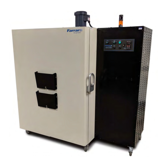
2.0 Introduction: The 4000 Series Farrar Scientific controlled rate freezer is designed to freeze or thaw product quickly or at a controlled rate. The controlled rate freezer operates using specific ramp and soak profiles tailored to the customer product requirements. The controller can be configured to ramp down and up in temperature and hold the set temperature for a specified time. -
Page 6: Specifications
4000 Series 3.0 Specifications: Size External: 75”W x 38”F-B x 80”H (190.2 x 96 x 2029 cm) Material External: Galvanized steel painted with Powdura Hybrid powder coat. Color: beige. Size Internal: 34”W x 27”F-B x 43”H (86.4 x 69.8 x 109 cm) This product is for Indoor Use Only. - Page 7 4000 Series Drain: External with heated evaporator pan, powered from the cabinet. Water Supply for water cooled condenser model 4102/4105 Tower water at ≤ 85F (29.5C) and ≥ 20 psi differential (1.38 Bar): Water flow rate at maximum load = 7.0 gpm (26.5 liters/ min) Water flow rate at average load = 4.5 gpm (15.0 liters/ min) Chilled water at ≤...
-
Page 8: Setup/ Installation
4000 Series 4.0 Setup/ Installation: Note: The receptacle for this unit must be positioned such that this unit can be rolled on its casters to achieve the following receptacle spacing: At least a 3 foot clearance in front of the receptacle, with a 30” wide working space, and headroom at least the height of the equipment. - Page 9 4000 Series Press the condensate drain p-trap into the right- angle cabinet drain connector under the cabinet until it bottoms out. Pivot p-trap drain end up. Place the evaporator pan under the drain outlet and pivot the p-trap down into the evaporator pan. (see photo below) Cabinet drain connector Connect the supplied electrical cord to the evaporator pan receptacle and plug the other end...
- Page 10 4000 Series Install (4) shelf clips in the duct sheet for each shelf (2) front and (2) in rear at the desired height. Spacing is approximately 0.5” (1.3 cm) for each shelf. Shelf Clip Place the shelves on the clips with the down flange facing the door opening. (see photo below) Shelf down flange Page 10 of 41...
- Page 11 4000 Series Three chamber (0.875” (2.22 cm)) access ports are provided; two on the rear of the cabinet and one on the left side. These ports may be used for customer provided chamber or sample monitoring. The ports are filled with insulation and both ends are plugged to reduce moisture infiltration.
- Page 12 4000 Series North America Electrical Plug: The unit comes installed with a Hubbell Locking Plug, Hubbell part number: CS8365C. Plug the unit into the matching receptacle Hubbell part number: CS8369 (not provided). The plug is 50A rated, 250VAC, 3P4W. Note: The rate chamber is powered by three phase and the refrigeration compressors are required to operate in a specific direction.
- Page 13 4000 Series b) We strongly recommend installation of ½” ball valve at 4102/4105 inlet (chilled or water tower) along with strainer and pressure gauge for trouble shooting and equipment testing purpose. The ball valve needs to be accessible during trouble shooting of equipment and can also be used for testing and servicing equipment.
-
Page 14: Control System
4000 Series 5.0 Control System: The unit consists of heating, cooling components, fans, and control components. The major cooling components include a compressor (heat moving component), condenser (heat rejection part), evaporator (heat absorption part) and expansion valve (refrigerant flow control devices). Heating is accomplished with the use of resistance heaters imbedded in the evaporator assembly. - Page 15 4000 Series 1. Power 2. Mode Switch/Cycle 4. Watlow USB Configuration 3. Cycle Complete Switch/Indicator Running Indicator Port Connect using USB-A to Indicator USB-B cable supplied with unit. 7. EZ1 button for 5. Start 6. Stop 8. Watlow Ramp and Pushbutton Pushbutton defrost...
- Page 16 4000 Series Control Description Profile Running Indicator Chamber Temperature C (Alarm and Error Codes will display when over - temperature alarms are Communications Indicator flashes triggered) when connected to a pc using the Watlow Configurator® software Unit Operating Status Output Indicators off: Unit is in standby Refrigeration Modulation, lit when full refrigeration is state or Control...
- Page 17 In case of a power failure of over 5 minutes, during a freeze or defrost profile, the unit will stop the current profile and will need to be restarted. In cases where the power fails for less than 5 minutes the profile will restart automatically. (This time can be changed, please contact Farrar Scientific for assistance) Defrosting the Evaporator Coil: The defrost mode is also a profile.
-
Page 18: Modifying Or Creating A Profile
4000 Series Control Security: The Watlow control write security can be set to disable all functions from the Watlow controller front panel. Please refer to the Watlow controller manual for detailed instructions. When write security is set to the highest write security level (level 0), configuring of the control system and profiling must be accomplished using the USB port supplied on the front of the control panel and the Watlow Configurator®... - Page 19 4000 Series Windows FTDI driver download: http://www.ftdichip.com/Drivers/VCP.htm It is important to only use the most up to date version of the FTDI USB driver, 2.12.28 as of this manuals printing. If an older version is used, programming parameters will not be loaded into the unit correctly causing unwanted unit operation.
- Page 20 4000 Series After clicking the next button above it is necessary to define the communications port that will be used on the PC as shown below. Clicking on the drop down will allow the user to select the appropriate communications port.
- Page 21 4000 Series The menu structure as laid out within this software follows: - Setup - Operations - Factory - Profile Navigating from one menu to the next is easy and clearly visible. Simply slide the scroll bar up or down to display the menu and parameter of choice.
- Page 22 4000 Series Lastly, when the configuration is complete click the "Finish" button at the bottom right of the previous screen shot. The screen that follows this action can be seen below Although the PM control now contains the configuration (because the previous discussion focused on doing the configuration on-line) it is suggested that after the configuration process is completed that the user save this file on the PC for future use.
- Page 23 10 steps to be programmed successfully. (If more than 10 steps are needed for Profile 1 and Profile 2, the start steps of each of the 3 Profiles can be changed to different step numbers. Please contact Farrar Scientific for aid in changing the appropriate settings).
- Page 24 4000 Series Wait For Process 1 -80ºC Wait Event 1 Wait Event 2 Day of Week Every Day Jump Step Jump Count End Type User Event 1 Tied to internal outputs on the controller Event 2 Event 1 must be ON and Event 2 OFF for this step type Soak Step This step type will hold the cabinet at the set point temperature defined in the previous step, for the specified time.
- Page 25 4000 Series Seconds Rate 0ºC Wait for Process Instance Must always be 1 for this step type Wait For Process 1 -80ºC The temperature waiting to be reached Wait Event 1 None Wait Event 2 None Day of Week Every Day Jump Step Jump Count End Type...
- Page 26 4000 Series Hours Minutes Seconds Rate 0ºC Wait for Process Instance Wait For Process 1 -18ºC Wait Event 1 Wait Event 2 Day of Week Sunday Jump Step Jump Count End Type Event 1 Event 1 and Event 2 must both be set to OFF in Event 2 this step type.
- Page 27 4000 Series Profile Examples Default profile 1 example Click on Profile1 step then Profile 1 Step 1. This step is the first to use when configuring profile 1. Note, the only options available for the Step Type (Time) are Target Set Point 1, Hours, Minutes, Seconds, Event 1 and Event 2.
- Page 28 4000 Series Screen 6 description: Profile 1 Step 2 is a wait for process step, the Wait for Process Instance 1 monitors the chamber temperature to reach the Wait for Process 1 temperature of -80C. Event 1 is on which continues to activate the refrigeration liquid, hot gas solenoid valves and profile running indicator on the mode switch.
- Page 29 4000 Series Screen 7 Screen 7 description: Profile 1 Step 3 is a Wait for Event step, the Wait for Event monitors the Wait for Event 1 and 2 if either is on then the profile waits at that step until the stop button is pressed. Event 1 is on which continues to activate the refrigeration liquid, hot gas solenoid valves and profile running indicator on the mode switch.
- Page 30 4000 Series Sample Profile Note this is a sample profile only and is not loaded into the controller. The step type settings from above should be followed to guarantee proper profile configuration. A profile controls the heating, cooling and internal circulation fan. This unit contains 40 profile steps broken down into 4 profiles of 10 steps each, profile 1 steps 1 thru 10, profile 2 steps 11 thru 20, profile 3 steps 21 thru 30 and profile 4 steps 31 thru 40.
- Page 31 4000 Series Profile 1 step 9: hold at -5C indefinitely or until stop is pressed. Event 1 must be On. This turns on the compressor and internal circulation fan. Event 2 must be On. With Event 1 and 2 on the Cycle Complete indicator will be flashing and the Cycle Running indicator will be on.
- Page 32 4000 Series The 1 indicates step 1 in profile 1. Other steps may be selected using the arrow keys. Range step 1 to 10. Press the advance key once. If 1 and P1 were left in the previous step then the lower display will look like the figure below.
-
Page 33: Sensor Validation
4000 Series 8.0 Sensor Validation: Control/display sensor validation may be performed by removing the sensor mounting plate, undoing the hook and loop fastener and extending the sensor cable to perform the needed validation. Refer to section 4.0 Setup and Installation item 10 for sensor mounting plate location. 9.0 Options: 9.1 Remote contacts terminal block The unit is supplied with remote signaling dry contacts (non-powered). - Page 34 4000 Series Remote Running Contacts Figure 9.2 – Remote contact terminal box with cover removed Door open alarm – horn and strobe (optional) In the event of a door opening while a profile or defrost cycle is running, there is a horn and strobe light installed on the top of the unit that will activate and remote contact terminals 5 &...
- Page 35 4000 Series Door open alarm – horn and strobe installation The door alarm electrical connection is located on top of the right side, black, control panel area. Remove the protective cap from the connector and discard. Page 35 of 41 3460006-17_serial series 5000000...
- Page 36 4000 Series Insert the strobe/alarm tower onto the connector. The white lines on the connector and strobe should align. Turn the strobe/alarm tower clockwise until the white line on the connector aligns with the end or the arrow. The tower is now locked to the connector.
-
Page 37: Troubleshooting
4000 Series 10.0 Troubleshooting: 1. Unit connected to power source, power switch on, no light on power switch or Watlow control. Verify input voltage on all 3 phase legs. On initial startup check all 3 phases. The rate chamber monitors for the correct phase sequence. -
Page 38: General Maintenance
4000 Series 11.0 General Maintenance Model 4000 series GENERAL MAINTENANCE Unit must be turned OFF & Unplugged during any and all maintenance/ service Hazards! Periodic Cleaning Beginning with the initial installation, the interior surfaces of the cabinet should be periodically wiped down with a solution of warm water and laboratory detergent. - Page 39 4000 Series Defrosting the Chamber Defrost the chamber on a regular basis. To defrost, complete the following steps: 1. Remove all products from chamber. 2. Turn off the freezer. 3. Let the freezer stand with doors open for at least 12 hours. This allows the interior to warm to room temperature.
-
Page 40: Factory Default Watlow Settings
Included on the flash drive is a PDF copy of the factory loaded Watlow Configuration. The file is in the “Farrar Scientific Model 4002 Documentation” folder on the flash drive. All highlighted text needs to be verified in the unit configuration before operation of the equipment. Not all parameters listed in this printout are active, dependent on higher priority settings. - Page 41 Serial Number: Date of Purchase: Purchase Order: IF YOU NEED ASSISTANCE: Farrar Scientific products support team are ready to answer your questions. In addition to technical support, we offer various accessories, extended warranty program, and validation services. Visit us at www.farrarscientific.com Contact us at 740.374.8300...
Need help?
Do you have a question about the 4000M Series and is the answer not in the manual?
Questions and answers