
Related Manuals for Farrar Scientific ULC Series


Summary of Contents for Farrar Scientific ULC Series
- Page 1 Model ULC Series ULC Series ULTRA LOW STORAGE CHAMBER 06012021ULC,Rev i Page 1 of 54...
- Page 2 Model ULC Series Revision Description Approval Date Original release 24 Apr 2020 Updated water connection size 16 Jul 2020 Updated with additional specs per NRTL inspection 09022020_a 02 Sep 2020 requests 09032020_b Added a maximum RH value to the spec...
- Page 3 Model ULC Series 06012021ULC,Rev i Page 3 of 54...
- Page 4 Farrar Scientific makes no representations or warranties with respect to this manual. In no event shall Farrar Scientific be held liable for any damages, direct or incidental, arising out of or related to the use of this manual.
-
Page 5: Table Of Contents
Model ULC Series -80C ULC Series Instruction Manual Table of Contents Receiving ....................Introduction ....................Specifications ................... Installation Requirements ................. Control System ..................Operation ....................a. Home Screen b. Setup Screen c. System Health Screen d. Information Screen e. Technical/Service Screen Managing User Accounts g. Setting System Clock Sensor Validation .................. -
Page 6: Receiving
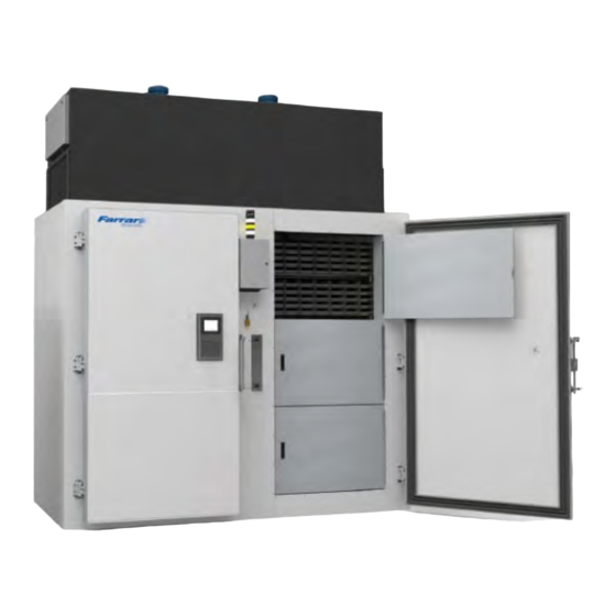
(2) power cords including two (2) redundant LCD controllers mounted onto each of the exterior doors. The ULC Series is not meant as a walk-in chamber, but rather a shelved unit for long term storage of samples and/or product at temperature between -20°C to -80°C. -
Page 7: Specifications
Farrar Scientific technical support team can assist users with any questions related to controller adjustments and settings. The ULC series internal blower motor will automatically turn off when either of the two exterior doors are opened. Should one of the two exterior doors be opened, the Controller LCD will display a “warning” icon, along with a “Yellow”... - Page 8 Model ULC Series Refrigeration Systems Refrigeration System Scroll Compressors Blower Motor Cfm/ l/m 500 / 14,158 Blower Motor Thermal Room Load 14,500 BTU/hr / 4.25 kW/hr Maximum Air Cooled BTU/ Kw Water Cooled BTU/ Kw < 1,550 BTU/Hr / 0.44 kW/hr Maximum...
- Page 9 Model ULC Series 24-hour power consumption - Defrost every 12 hours 66.66 kWh / 24hr. (2 defrost events) 2 to 5 minutes generator delay start time Backup Generator to ULC from power outage During Power Off All ULC operation and display are Off...
-
Page 10: Installation Requirements
Model ULC Series 4.0 Installation requirements 1. For installation of the Construct on Site chamber and for installation of the refrigeration systems, please refer to the Installation Manual. If lifting unit, place lift forks under center of enclosure. 2. For proper air flow, ensure there is a minimum of the following distances from the unit to the nearest wall or ceiling: Back of unit: 14.0 in. -
Page 11: Control System
Model ULC Series b. To allow for movement of the equipment during servicing, we recommend using ½” industrial grade flexible hose; 8’ (2.5m) in length. c. We strongly recommend installing a 1/2” ball valve at the water inlet along with a strainer and pressure gauge. - Page 12 ENT (enter). Review the Setup, System Health, Unit Information and Technical Service screens to input your required values and familiarize yourself with the features of the ULC series. 06012021ULC,Rev i Page 12 of 54...
-
Page 13: Home Screen
Model ULC Series a. Home Screen Home Screen Previous Screen Next Screen System Setup This icon will display the system setup screens for alarms, alarm delays, defrost cycles, screen settings, service intervals and factory defaults in sequential order. System Health This icon will display the general system health screens for primary cooling, defrost status and system critical temperatures in sequential order. - Page 14 Model ULC Series Alarm Silence This icon will be displayed during an active alarm. Touching this Alarm Silence Icon will silence the audible alarm for a period of time set up by the user. Should the alarm condition remain active, the audible will sound again at the end of the delay period.
-
Page 15: Setup Screen
Model ULC Series Set-up Screen Home Screen Each screen will display Next Screen Previous screen the current internal chamber temperature RETURN TO HOME SCREEN RETURN TO PREVIOUS SCREEN GO TO NEXT SCREEN IN THIS SEQUENCE ALARM HIGH: Touch the “Alarm High” display. A numerical entry keypad will be displayed. Enter the high temperature alarm set point. - Page 16 Model ULC Series REFRIG ASSIST: The ULC series is equipped with a refrigeration assist feature. When the chamber warms up by the programmed Refrig Assist temperature, the Standby system will run to assist the Primary system to return the chamber to the temperature set point.
- Page 17 Model ULC Series SETUP 3: DEFROST CYCLE TIME: Touch “Defrost Cycle Time” display to enter the interval time period between automatic defrosts. The available range is 2 to 168 hours. The Factory Default is 12 hours. 12 hours is the recommended setting and should not be changed without consulting the factory.
- Page 18 Model ULC Series Press to go to the next screen. SETUP 4: SINGLE/DUAL SYSTEM: Touch either “Select Single Operation” or “Select Dual Operation”, denoting if there are one or two refrigeration systems operational on this chamber. The software to automatically switch between the two systems.
- Page 19 Model ULC Series The door switches will be ignored. The refrigeration system will continue to run under temperature control, regardless whether the doors are open or closed. When this mode is selected, there will be a message on the Home Screen stating: WARNING: DOOR SWITCH DISABLED to remind the operator that the door switch is being ignored.
- Page 20 Model ULC Series Press to go to the next screen. SETUP 6: RESET SETTINGS TO FACTORY DEFAULTS: Touch the right arrow to reset all control settings to factory default values. A second screen will display to confirm the reset. Touching the green check mark on the second screen will reset all settings the factory values.
-
Page 21: System Health Screen
Model ULC Series Press to return to the Home screen. SYSTEM HEALTH SCREEN System Health H1 shows the operating status of its system. The information will include: Primary - Cooling or Cycled Off Standby - Off or Assisting in Cooling ... - Page 22 Model ULC Series VIEW ALARM LOG: Touch the arrow to view a list of all the alarms that have occurred on the system, including the date and time of occurrence and the acknowledgement. ALARM LOG The Alarm Log Screen shows all current and past alarm conditions that were detected by the control system.
- Page 23 Model ULC Series Return to Home Screen – Press this button to close the Alarm Log Screen and return to the Home Screen. SYSTEM HEALTH 2: DEFROST CYCLE TIME: Displays the time interval between evaporator defrosts when this system is running as primary. The value cannot be changed on this screen. See Setup screen number 3.
- Page 24 Model ULC Series SYSTEM HEALTH 3: Displays the present value of various key temperatures in the refrigeration system. These values are mainly useful to technical and maintenance personnel. Press to return to the Home screen. 06012021ULC,Rev i Page 24 of 54...
-
Page 25: Information Screen
Model ULC Series INFORMATION SCREEN Electrical Requirements Operating Pressure Refrigerant Info info Serial Number Production Date Displays the information that is typically included on the serial tag label Press to go to the next Information screen INFORMATION 2: Model HMI Software... -
Page 26: Technical/Service Screen
Model ULC Series Technical/Service Screens TECHNICAL 1: Note: Manual, OFF and Auto modes require Administrator privileges to access MANUAL BUTTON: Touch the “Manual” button to enter Manual mode. This mode allows individual manual On/Off operation of the various components of the system. - Page 27 Model ULC Series TECHNICAL 2: Note: Tech Summary, View Temps – S.P. & Actual and View Timers – S.P. & Actual require Administrator privileges to access. TECH SUMMARY: Touch the “Tech Summary” right arrow icon to enter the detailed technical screens.
- Page 28 Model ULC Series TECHNICAL 3: PRESENT TEMP PROBE VALUE: Displays the present reading from the temperature control probe. DESIRED PROBE VALUE: Touch the display and use the keypad to enter the control probe value based on an independent temperature sensor.
-
Page 29: Managing User Accounts
Model ULC Series f. MANAGING USER ACCOUNTS To reach the User Account Screens, start at screen TECHNICAL 2. Press the Arrow to go to the TECH SUMMARY Screen. The Password keypad will display. To manage user accounts, you must have Administrator access rights. The Factory Administrator account is “Tom1”... - Page 30 Model ULC Series To set up the new user accounts and passwords (for the first time), enter the Factory Administrator account information and press ENT. The display will return to the Technical Menu (T2) screen. Press the arrow again to view the Tech Summary screen. Once you have your own Administrator account, scroll using the up and down arrows to find your Username.
- Page 31 Model ULC Series On the MAIN MENU SCREEN, press the VIEW OPTIONS SCREEN button. MAIN MENU VIEW CLOSE VIEW INFO PRACTICE MAIN INPUT SCREEN MENU SCREEN VIEW VIEW DEF VIEW DELAY TEMP SET TIMER SET TMRS & PT. & PT &...
- Page 32 Model ULC Series On the VIEW OPTIONS SCREEN, press the OPEN USER ACCOUNTS button. OPEN BRIGHTNESS SCREEN CHAMBER TEMPS NOT SYNC’D SYNC OPEN USER OPEN CHAMBER ACCOUNTS SYSTEM TEMPS MODE DISPLAY SOFTWARE VERSION: 1XXX.B.1.35 CPU SOFTWARE VERSION; 1xxx.b.127 DOOR OPEN TOO LONG DELAY...
- Page 33 Model ULC Series SELECT USER ACCOUNT: To Edit the profile of an existing account, press the up or down arrow to scroll to that account’s profile and press the Edit button. User ID User Name John1 Password **** Operator Reader...
- Page 34 Model ULC Series SELECTING SECURITY GROUP(S): Select the security groups you wish to grant to this account. A brief description of privileges given to each security group is listed below. After selecting the desired security groups, press the “Close” button.
- Page 35 Model ULC Series After pressing the “OK” button on the account edit screen, the message screen will indicate the changes have been saved. Press OK to return to the accounts screen. User ID User Name John 1 Password **** Succeed...
- Page 36 Model ULC Series ADDING A NEW USER ACCOUNT: On the USER ACCOUNT screen, press the “Add” button. User ID User Name John1 Password **** Operator Reader Security Detail Group Edit Del. A blank user account profile will appear. Touch the User Name.
- Page 37 Model ULC Series A keypad will be displayed. Enter the username and press ENT. Lower Case & Sign <CUR >CUR Note: There are selection buttons on the left side of the keypad for lower case or numbers and symbols. Touch the Password area. A keypad will be displayed. Enter the Password and press ENT.
- Page 38 Model ULC Series After all the account profile information has been entered, press the OK button. User ID User Name JANE1 Password **** Succeed Add User. A message will be displayed confirming that the account profile has been saved. Press OK to return to the accounts screen.
- Page 39 Model ULC Series Press VIEW MAIN SCREEN OPEN BRIGHTNESS SCREEN CHAMBER TEMPS NOT SYNC’D SYNC OPEN USER OPEN CHAMBER ACCOUNTS SYSTEM TEMPS MODE DISPLAY SOFTWARE VERSION: 1XXX.B.1.35 CPU SOFTWARE VERSION; 1xxx.b.127 DOOR OPEN TOO LONG DELAY DOOR OPEN ELAPSED TIME LOW TEMP ALARM SET POINT °c...
- Page 40 Model ULC Series You will be returned to the TECH SUMMARY SCREEN Press the HOME button. VIEW MAIN MENU OTHER SIDE NOT PRESENT Ultra Low Chamber +18.4 CHAMBER TEMP °C CHAMBER SET POINT °C HAND AUTO SIDE B LOG IN...
-
Page 41: Setting System Clock
Model ULC Series g. SETTING SYSTEM CLOCK Note: Administrator privilege is required to set the system date and time. The system clock can be set using the hidden system menu. This menu is accessed by touching and holding the upper left corner of the display screen. - Page 42 Model ULC Series On the System screen, select the Main Menu button. SYSTEM MODE TOP PAGE OFFLINE MAIN MENU MAC Address 00:03:7B:09:08:4F IP Address 192.168.3.231 2021/APRIL/08/THURS 11:52:15 ENG/JPN « » BRIGHTNESS 28 On the Main Menu page, Press “Clock Setting”.
-
Page 43: Sensor Validation
Model ULC Series 7.0 Sensor Validation Each system has an independent Control/display sensor (100 OHM 3 wire Platinum RTD, +/- 0.15 °C). Calibration may be performed using the Calibration screens on Technical Screen 3. 8.0 Alarms Remote alarm contacts terminal block The ULC is supplied with remote alarm signaling dry contacts (non-powered). - Page 44 Model ULC Series Terminals Position Description Open Doors are open Closed Doors are closed Open General alarm Closed No alarm conditions Light Tower 06012021ULC,Rev i Page 44 of 54...
- Page 45 Model ULC Series Light Tower – Located between the doors Alarms Light Settable System A System B Displays Tower Range Power Fail Temperature High Alarm A/V/C A/V/C Alarm Icon -80°C to 30°C Temperature Low Alarm A/V/C A/V/C Alarm Icon -99°C to -40°C...
-
Page 46: External Access Ports
Model ULC Series Compressor 1 fail low amps (<2 amps) Compressor 2 fail high amps (>20 amps) Alarm Silence This icon will be displayed during an active alarm. Touching this Alarm Silence Icon will silence the audible alarm for a period of time set up by the user. Should the alarm condition remain active, the audible will sound again at the end of the delay period. -
Page 47: Troubleshooting
Model ULC Series 10.0 Troubleshooting 1. Unit connected to power source, display not on. a. Verify input voltage at receptacle. b. On initial startup, qualified electrician or personnel should check the receptacle for voltage. c. Check that main circuit breaker, located in the control enclosure upper left corner, is not tripped. -
Page 48: General Maintenance
Model ULC Series 11.0 General Maintenance ULC/ULCI GENERAL MAINTENANCE Unit must be turned OFF & Unplugged during any and all maintenance/ service Hazards! Periodic Cleaning Beginning with the initial installation, the exterior surfaces of the ULC/ULCi should be periodically wiped down using isopropyl alcohol or commercial grade glass cleaner. - Page 49 Model ULC Series 2. Remove side panel cover of each refrigeration section to access the compressor area 3. Manually flush the valve and piping before and after installing, repairing, or replacing a valve to remove filings, chips, or other foreign matter. Manual flushing does not affect valve adjustment.
- Page 50 Model ULC Series Vacuum Relief Ports Periodically check each vacuum relief ports located on the inside of each exterior door. Keep the vacuum relief ports clean and frost free by wiping with a soft cloth. The vacuum relief ports must be kept clear of ice/snow. Failure to keep the vacuum relief ports clean will cause longer than normal wait time before door can be re-opened due to the vacuum created by the contraction of the air that entered the chamber.
-
Page 51: Factory Default Control Settings
Model ULC Series 12.0 Factory Default Settings All settings may be returned to factory default settings. Refer to the details the Setup section, screen 6. 06012021ULC,Rev i Page 51 of 54... -
Page 52: Warranty - North America
Model ULC Series 13.0 Warranty - North America Every Farrar Scientific -80C ULC freezers are backed by a comprehensive full one (1) years parts & labor warranty coverage on all refrigeration, controls and electrical components. ULC wall panels are covered by a one (1) year warranty. -
Page 53: Warranty - International
Model ULC Series 14.0 Warranty - International Every Farrar Scientific -80C ULC freezers are backed by a comprehensive fourteen (14) month parts only warranty coverage on all refrigeration, controls and electrical components (FCA Marietta, OH). ULC wall panels are covered by a one (1) year parts only warranty (FCA Marietta, OH). - Page 54 Model ULC Series Important information for your future reference and when contacting Farrar Scientific or local Distributors. Please have the following information readily available: Model Number: Serial Number: Date of Purchase: Purchase Order: IF YOU NEED ASSISTANCE: Farrar Scientific products support team is ready to answer your questions.
Need help?
Do you have a question about the ULC Series and is the answer not in the manual?
Questions and answers