Table of Contents
Advertisement
Quick Links
Advertisement
Chapters
Table of Contents

Related Manuals for Anemoment TriSonica Mini


Summary of Contents for Anemoment TriSonica Mini
- Page 1 ANEMOMENT LLC TriSonica Mini Sensors User Manual...
- Page 2 Release Date 9 July 2021 Anemoment LLC...
- Page 3 NEMOMENT TriSonica Mini Sensors: User Manual 2021 Anemoment LLC 353 Main Street Longmont, CO 80501 Phone 720.600.7241 • Fax 720.223.7504 Email: info@anemoment.com Release Date 9 July 2021 Anemoment LLC...
- Page 4 NOTES: Sensor Unit Numbers: ___________________________________________________ Purchase Date: _________________________________________________________ Release Date 9 July 2021 Anemoment LLC...
-
Page 5: Table Of Contents
Table of Contents Hello World! ..........................5 Guide to User Manual ......................5 The TriSonica Mini Family of Products ..................5 Tell Us! ............................ 6 Limitation Alerts........................6 Compact Fluorescent Lamps ....................6 Electro-Mechanical Motors and Magnetic Sensors .............. 6 Ice and Snow ........................ - Page 6 Absolute Pressure ........................29 Tilt ............................29 Compass ..........................29 TROUBLESHOOTING your TriSonica Mini Sensor ..............31 Common Set-up Errors ......................31 Symptom: The TSM Sensor doesn’t seem to be doing anything.........31 Symptom: There is no serial data coming from the TSM Sensor.........31 Symptom: The TSM Sensor sends garbled data.
-
Page 7: Hello World
Chapter Hello World! Welcome to the User Manual for the TriSonica Mini (TSM) family of products from Anemoment. We hope you find this information useful and wish you every success in your research. We welcome comments and questions about this manual by email at info@anemoment.com. -
Page 8: Tell Us
Screenshots and photos can be extremely helpful! Limitation Alerts Anemoment wants you to get the best possible use from your TSM Sensor investment, and we understand that each User has a unique idea they want to create. You know best what you are trying to accomplish. -
Page 9: Ice And Snow
Term, to review the data stream and to communicate with or configure the sensor. Available for download at the Anemoment website is a rudimentary User interface app for use on Windows™ operating systems; this app is not suitable for data logging functions. - Page 10 Release Date 9 July 2021 Anemoment LLC...
-
Page 11: Tsm Body, Drawings, & Mounting Specifications
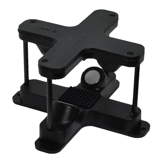
ZERO orientation of the TSM Sensor. TSM-FB The TSM-FB features a flat base with four mounting points for connecting to a User-supplied mounting platform. Figure 2: TSM-FB DRAWING Release Date 9 July 2021 Anemoment LLC... -
Page 12: Considerations For User-Supplied Mounting Platform For Tsm-Fb
5.5-mm hole positioned at the Gore-Tex™ Vent to allow for water vapor and air pressure exchange. TSM-FB Tripod Mounting Plate Anemoment offers an optional 3d-printed mounting plate for attaching the TSM-FB to a standard platform or camera tripod. This mounting plate features a brass ¼-20 threaded insert. -
Page 13: Connecting Up
Specially configured TSM-FB may have different color wires in the place of or in addition to these four. Please refer to instructions accompanying the specially configured TSM-FB for more information. Connecting the TSM-FB to Other Anemoment Products USB ADAPTER: •... -
Page 14: Tsm-Pm
The TSM-PM contains a female 12 Pin circular connector that connects to a male 12 Pin Circular IP67 connector. Cables with connectors may be purchased from Anemoment in 2m, 5m, 10m, and 20m lengths. Customized cables and mating connectors may be purchased directly from Samtec.com (see https://www.samtec.com/products/mcp for information... -
Page 15: Table 5: Tsm-Pin Description & Cable Wire Colors
EIA232 or LVTTL-UART mode with the LACK settings of 115200,8,N,1 regardless of the software settings of the instrument. IGHT 3.3V LVTTL-UART Serial Data Output. REEN Ground connection. See the description for Pin #2 Release Date 9 July 2021 Anemoment LLC... -
Page 16: Connecting The Tsm-Pm To Other Anemoment Products
Connecting the TSM-PM to Other Anemoment Products USB ADAPTER: Use the Single-Terminated • blunt-cut cable to connect the TSM-PM to the USB Adapter. Separate out and strip 3mm of the ends from the Yellow, Blue, Red, Black, and Brown wires from the blunt-cut end of the cable. -
Page 17: Data Output
TSM Sensor and allows data pass-through, the Serial Data Stream from the TSM Sensor can be viewed by using a Terminal Emulator app such as Tera Term or with the TriSonica Mini User App downloadable at https://anemoment.com/resources/. Serial Data Format The TSM outputs data in an ASCII character string ending with carriage return and line feed characters. -
Page 18: Custom Delimiters (New In 2.0)
S: 05.3,D: 107,U:-01.5,V: 04.9,W: 01.3,T: 22.2 Error Codes When the TriSonica Mini firmware detects an error, it outputs an error code in the data stream in all the affected parameters. All error codes appear in the format of “-99.x”. The decimal value of the error code varies with the error type. -
Page 19: Customizing The Tsm Sensor Configuration
If no User input is received while the Serial Menu is inactive for one minute, the TSM returns to sampling mode and any changes made are not stored in the non-volatile memory. Release Date 9 July 2021 Anemoment LLC... -
Page 20: Command Line Interface - Basic
“[“ and “]” are optional. NOTE: We attempt to make the TSM CLI self-documenting, so with future Firmware Releases, the detailed help for each command may be more current than appears in the following table. Release Date 9 July 2021 Anemoment LLC... -
Page 21: Table 9: Serial Commands In The Command Line Interface
Hide, Tag, Untag, and Decimal Commands section in this document. levelcalibrate YES Start a level calibration cycle. (Not available on TSM-WS) See the compass calibration section of this document for more details about the compass calibration procedure. Release Date 9 July 2021 Anemoment LLC... - Page 22 Set or Show the data output rate of the sampled data parity [odd|even|none [now]] Set or Show the current parity setting programupdate [YES] Use the TriSonica Mini Program Update Utility provided by Anemoment. show [<param>] Show Display Parameter or Groups. See the Show, Hide, Tag, Untag, and Decimal Commands section in this document.
-
Page 23: Command Line Interface - Expert Mode
Sets or shows the low power configuration parameters. Low power mode can be woken internally, or externally. Do not use the external wake mode on a TSM-WWS. Release Date 9 July 2021 Anemoment LLC... - Page 24 South. The “ati” setting defines the positive U as being from the North, and positive V as being from the West. The “otsm” setting matches the original TriSonica Mini output definition of positive U as being form the North, and positive V as being from the East.
-
Page 25: Application Programming Interface (New In 1.9)
TSM-PM then waits until the next trigger before sampling again. If the trigger is too fast to complete all the samples, the TSM-PM will shorten the number of samples taken to maintain the external trigger rate. Release Date 9 July 2021 Anemoment LLC... -
Page 26: Display Command
This value is controlled by the paramdelim command. The default value for both delimiters is a space character. Release Date 9 July 2021 Anemoment LLC... -
Page 27: Calibration Procedures And System Memory
TSM into as many orientations as possible using a three-dimensional figure eight pattern. Enter “nvwrite” to store the values in non-volatile memory. Release Date 9 July 2021 Anemoment LLC... - Page 28 These results are stored in the TriSonica Mini sensor’s memory to supply the known distance from which time-of-flight changes are detected. Packed in the box with each TriSonica Mini sensor you will find a certification that the sensor passed this power-up and calibration testing, and the distance values were stored.
-
Page 29: Wind Direction Scale Command (Wd540)
540 degrees and again at 180 degrees to display data. Non-Volatile Parameters The TriSonica Mini operates with a copy of its configuration parameters in volatile memory (RAM). When changes are made using the CLI, the parameters are updated in the volatile memory. - Page 30 Release Date 9 July 2021 Anemoment LLC...
-
Page 31: Tsm Sensor Meteorological Data Collection
The average of the ultrasonic temperature is used to calculate the humidity from the dew point. An issue seen during testing occurred when the TriSonica Mini was removed from a warm 90% humidity environment to a cooler 30% environment. The quick change caused condensation inside the unit and it displayed humidity greater than 100% until the condensation evaporated and equalized through the vent. - Page 32 Release Date 9 July 2021 Anemoment LLC...
-
Page 33: Troubleshooting Your Trisonica Mini Sensor
TROUBLESHOOTING your TriSonica Mini Sensor Chapter Common Set-up Errors Symptom: The TSM Sensor doesn’t seem to be doing anything. Action: Place the TSM Sensor near your ear and listen for a quiet fast ticking sound. • If you hear no sound, confirm the device the TSM Sensor is connected to has power. -
Page 34: Updating Tsm Sensor Firmware
• Updating TSM Sensor Bootloader (New in 2.0) In the TriSonica Mini program memory are two programs, the TriSonica Sensor application, and a bootloader. During a reset or power on, the bootloader checks to determine if the sensor application is valid. If the sensor application is valid the bootloader turns over control to the sensor application. -
Page 35: Warranty And Disclaimer
Product damaged due to improper installation or use. Anemoment’s sole obligation under this Warranty shall be to repair, replace, or refund purchase price of the applicable Product, at its sole option, provided that Anemoment is given timely notice of the defect. - Page 36 Table 7: TSM-PM DATA LOGGER SCREW TERMINAL WIRING POSITIONS ........14 Table 8: SERIAL MENU FUNCTIONS ....................18 Table 9: Serial Commands in the Command Line Interface ............19 Table 10: Serial Commands In Expert Mode ................21 Release Date 9 July 2021 Anemoment LLC...
Need help?
Do you have a question about the TriSonica Mini and is the answer not in the manual?
Questions and answers