
Related Manuals for Glomstad Motor GM - U95 PRO


Summary of Contents for Glomstad Motor GM - U95 PRO
- Page 1 GM - U95 PRO MAINTENANCE MANUAL WHEEL BALANCER WITH MICRO-PROCESSOR 1 / 28 REV. 01 2020...
- Page 2 PRINTING CHARACTERS AND SYMBOLS Throughout this manual, the following symbols and printing characters are used to facilitate reading: Indicates the operations which need proper care Indicates prohibition Indicates a possibility of danger for the operators BOLD TYPE Important information 2 / 28 REV.
-
Page 3: Table Of Contents
CONTENTS INTRODUCTION 1.1 INTRODUCTION MACHINE IDENTIFICATION DATA 1.3 MANUAL KEEPING GENERAL INFORMATION 2.1 GENERAL SAFETY STANDARD SAFETY DVICES 2.3 INTENDED USE 2.4 GENERAL CHARATERISTICS 2.5 MACHINE DESCRIPTION 2.6 TECHNICAL SPECIFICATION TRANSPORTATION, UNPACKING AND STORAGE 3.1 TRANSPORTATION 3.2 UNPACKING 3.3 STORAGE COMMISSIONING 4.1 SPACE REQUIRED 4.2 SHAFT ASSEMBLY... -
Page 4: Introduction
CHAPTER 1 – INTRODUCTION INTRODUCTION Thank you for purchasing a product from the line of wheel balancer. The machine has been manufactured in accordance with the very best quality principles. Follow the simple instructions provided in this manual to ensure the correct operation and long life of the machine. Read the entire manual thoroughly and make sure you understand it. -
Page 5: General Information
CHAPTER 2 – GENERAL INFORMATION GENERAL SAFETY • The wheel balancing machine should only be used by duly authorized and trained personnel. • The wheel balancing machine should not be used for purposes other than those described in the instruction manual. •... -
Page 6: Machine Description
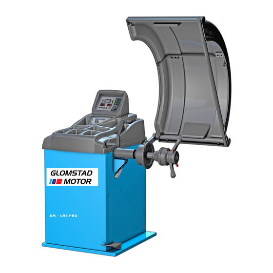
• Display in grams or ounces, in mm or inch • Anchor-down installation unnecessary MACHINE DESCRIPTION A: Display panel Fig. 1 B: Measuring gauge A/D C: Wheel guard D: Quick locking nut E: Wheel shaft F: Machine body G: Foot brake H: Wheel weight tray I: LED lighter J: Control panel... -
Page 7: Transportation, Unpacking And Storage
CHAPTER 3 – TRANSPORTATION TRANSPORTATION, UNPACKING AND STORAGE AND STORAGE TRANSPORTATION The machine must be transported transported in its original packaging • and kept in the position shown shown on the package itself. • The packaged machine may may be moved by means of a fork lift truck of suitable capacity. -
Page 8: Commissioning
CHAPTER 4 – COMMISSIONING COMMISSIONING 4.1 SPACE REQUIRED When choosing the place of installation, make sure that it it complies with current safety at work regulations regulations. Do not operate the balancer while it is on the pallet. o not operate the balancer while it is on the pallet. •... -
Page 9: Wheel Guard Mounting
4.3 WHEEL GUARD MOUNTING • Mount the wheel guard onto the guard arm by the supplied screws according to Fig. • Check the micro switch is held down when the wheel guard is closed. Adjust it if necessary. Guard shaft Frame Nut M8 Screw M8X45... -
Page 10: Control Panel And Menu Function
CHAPTER 5 – CONTROL PANEL AND MENU FUNCTION 5.1. DISPLAY PANEL Press buttons only with your fingers. Never use the counterweight pincers or other pointed objects. When the beep signal is enabled, pressing of any push button is accompanied by a “Beep”. -
Page 11: Control Panel
5.2. CONTROL PANEL Press buttons only with your fingers. Never use the counterweight pincers or other pointed objects. When the beep signal is enabled, pressing of any push button is accompanied by a “Beep”. Fig. 8 – CONTROL PANEL 1. Unbalance reading selection 2. -
Page 12: Menu Function
MENU FUNCTIONS (figure 9) OPT function DIAMETER mm/inch WIDTH mm/inch WHEEL GUARD on/off Start from GUARD closing Approx. 1-5g or 0.1-0.25oz BEEP on/off Entry SET UP menu SELF-DIAGNOSIS g/oz unbalance measurement unit See SELF-CALIBRATION chapter Press to exit any function. 12 / 28 REV. -
Page 13: Operation Of The Wheel Balancer
CHAPTER 6 – OPERATION OF THE WHEEL BALANCER Do not use the machine until you have read and understood the entire manual and the warning provided. The wheel guard must not be opened before the wheel stops. The STOP button serves to stop the machine immediately in emergencies. - Page 14 • On most wheels, the inner side of the wheel hub usually has the most uniform surface for wheel balancing. Always center the wheel by the most uniform shaped side of the hub to achieve the most accurate balance. • Regardless of mounting type, always make sure that the wheel is forced firmly against the shaft faceplate and that the quick locking nut is tightened.
-
Page 15: Wheel Data Entry
WHEEL DATA ENTRY Before balancing a wheel, wheel data must be entered. 6.3.1 WHEEL DATA ☆ Fig. 12 – STANDARD MODES Fig. 13 – MODE For STANDAD MODES, measure the wheel dimensions as shown in the figure 12. ☆ MODE, measure the wheel dimensions as shown in the figure 13. In this machine, A and D values also can be entered either manually or automatically. -
Page 16: Balancing Mode
BALANCING MODE 6.4.1 DYNAMIC MODE The dynamic mode is used for most passenger and light truck wheels using the most common location for corrective weights. Clip-on weights are placed on the inner and outer sides of the rim at 12 o’clock position. -
Page 17: Standard Alu Mode
6.4.3 STANDARD ALU MODE All the ALU modes are dynamic balance. Choose the option that best fits the available locations as shown in the figure 18 From the measurement screen, press to select the modes ALU1 ALU2 ALU3 ALU4. Fig. 18 Balancing of light alloy rims with application of adhesive weights on the rim shoulders. - Page 18 ☆ 6.4.4 MODE This is a special ALU mode for precise and fast application of the adhesive weights on the rim by means of the automatic gauge. There are two modes of ALU1 ☆ and ALU2 ☆ . to select ALU1 ☆ mode. Press Choose two positions on the rim where can be applied with the adhesive weights and then measure the dimensions as shown in the diagram (Fig.
- Page 19 to select ALU2 ☆ mode. Press This is the combination application: clip-on weight inside and attach the adhesive weight on rim. Measure the dimensions as shown in the diagram (Fig. 22). Pay attention to press to memorize A1 dimension which should be measured at first, then measure AE dimension which will be memorized automatically.
-
Page 20: Alu Mode
6.4.5 SPLIT FUNCTION The SPLIT function is used to position the adhesive weight behind the wheel spokes so that they are ☆ no longer visible. It is advisable to use this function only in the static unbalance or in the mode. -
Page 21: Unbalance Optimization (Opt)
6.4.6 UNBALANCE OPTIMIZATION (OPT) This function is used to determine the best mating of tire and rim that will result in the least amount of total unbalance of the wheel. It severs to reduce the amount of weight to be added in order to balance the wheel. -
Page 22: Set Up
CHAPTER 7 – SET UP SELF-DIAGNOSIS Fig. 25 Diagnosis of phase Rotate the wheel in direction of rotation, the readouts display from 0 to 255. Rotate the wheel in reverse direction of rotation, the readouts displays from 255 to 0. Diagnosis of inner piezo Push the balancing shaft from any direction, the readouts change. -
Page 23: Calibration
CALIBRATION To access SELF-CALIBRATION menu, refer to Fig. 8. For the self-calibration proceed as follows: Fig. 26 Weight calibration Distance (A) gauge calibration Diameter (D) gauge calibration Width (B) gauge calibration 23 / 28 REV. 01 2020... - Page 24 7.2.1 WEIGHT CALIBRATION Make sure to entry the exact date of the wheel mounted. Entry of incorrect data would mean that the machine is not correctly calibrated, therefore all subsequent measurements will be incorrect until the new self-calibration is performed with the correct data. Fig.
- Page 25 7.2.3 CALIBRATION OF D GAUGE Place the supplied calibration meter on the HIGER Fig. 30 PROFILE surface of shaft (“0” position) and then set the gauge tip into the lower hole of the meter. Place the supplied calibration meter on the HIGER Fig.
-
Page 26: Maintenance
CHAPTER 8 – MAINTENANCE GENERAL WARNINGS Unauthorized personnel may not carry out maintenance work. • Regular maintenance as described in the manual is essential for correct operation and long lifetime of the machine. • If maintenance is not carried out regularly, the operation and reliability of the machine may be compromised. -
Page 27: Errors And Trouble-Shooting
CHAPTER 9 – ERRORS AND TROUBLE-SHOOTING ERROR DISPLAY During machine operation, various cause of faulty operation can occur. If defected by the micro- processor, they appear on the display as follows: ERRORS: MEANING: SOLUTION: Err -0- The machine is not preset up by the Call for the technical service. -
Page 28: Accessories
CHAPTER 10 – ACCESSORES 10.1 STANDARD ACCESSORIES 1. TR40X3 Quck locking nut 2. Pressure cup 3. P1-12001W Cone D.44-70 4. P1-12002W Cone D.59-82 5. P1-12003W Cone D.78-111 P1-12004W Cone D.85-132 10.2 OPTIONAL ACCESSORIES PF-211 Universal flange Universal flange for wheels with/without central hole, suitable for any vehicle wheel with 3-4-5 holes.
Need help?
Do you have a question about the GM - U95 PRO and is the answer not in the manual?
Questions and answers