Table of Contents
Advertisement
Quick Links
Advertisement
Table of Contents

Related Manuals for Arc Machines M96

Summary of Contents for Arc Machines M96
- Page 1 M96 WELD HEAD OPERATION MANUAL...
- Page 2 OPERATION MANUAL NOTICE This document and the information contained herein is the property of Arc Machines, Inc.. It is proprietary and submitted and received in confidence. It shall be used only for the purpose for which it is submitted and shall not be copied in whole or in part without the prior expressed written permission of Arc Machines, Inc.
-
Page 3: Table Of Contents
MODEL 96 TUBE TO TUBESHEET WELD HEAD OPERATION MANUAL Table of Contents Chapter Page No. Introduction……………………….. …… 3 Unpacking………………………………. 4 Cable hook up…………………………. Rotation (speed) Calibration…………. Mandrel installation……………………… 9 Electrode geometry & installation……… 11 Gas chambers…………………………. Nose ring……………………………….. Shielding gas…………………………… 10.0 Cleaning and maintenance……………... -
Page 4: Introduction
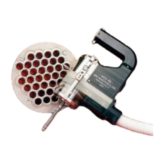
MODEL 96 TUBE TO TUBESHEET WELD HEAD OPERATION MANUAL 1.0 INTRODUCTION The Model 96 Weld Head is designed for Tube to Tubesheet fusion welding, using the GTAW process. Tubes can be flush, slightly projected above, or recessed below the tubesheet. It is designed to accommodate tube sizes from 0.37 (9.4mm) I.D. -
Page 5: Unpacking
The integral 10ft. (3 meter) cable contains electrode power, shielding gas, motor (electrode rotation) control, coolant (in/out) and a ground cable. CAUTION A thorough understanding of the Arc Machines Power Supply being used is required before installation or operation is attempted. 2.0 UNPACKING When unpacking the weld head use extreme caution in removing the plastic bag covering the cable connectors. -
Page 6: Cable Hook Up
MODEL 96 TUBE TO TUBESHEET WELD HEAD OPERATION MANUAL 3.0 CABLE HOOK UP CAUTION Always turn the power supply off before making any cable connections. The Model 96 weld head comes supplied with an integral 10ft (3 m) cable. This cable is NOT connected directly to the power supply. It must be mated to the power supply via an adapter pig-tail or adapter cable. - Page 7 MODEL 96 TUBE TO TUBESHEET WELD HEAD OPERATION MANUAL 3.0 CABLE HOOK UP (contd.) 3.2 To connect the male to female (chrome) gas fittings, unscrew the (4-40) socket head screw to allow the latch to open far enough to fully seat the two fittings.
-
Page 8: Rotation (Speed) Calibration
MODEL 96 TUBE TO TUBESHEET WELD HEAD OPERATION MANUAL 2.0 CABLE HOOK UP (contd.) Fig. 4 3.4 Slide the boots together securely to protect the connectors and fittings from dirt, and to prevent the power and ground connectors from coming in contact with each other. Fig. 4. 3.4 Before connecting the air line, first be sure that the air actuation switch on the handle is in the up (off, un-actuated) position. - Page 9 MODEL 96 TUBE TO TUBESHEET WELD HEAD OPERATION MANUAL 4.0 ROTATION (SPEED) AUTO-CALIBRATION (contd.) Fig. 5 4.1 ROTATION (SPEED) MANUAL CALIBRATION Follow the instructions on your power supply in making adjustments to the potentiometer. Repeat this procedure until the power supply indicates that the head is calibrated. For power supplies that do not have auto calibration software.
-
Page 10: Mandrel Installation
MODEL 96 TUBE TO TUBESHEET WELD HEAD OPERATION MANUAL 4.1 ROTATION (SPEED) MANUAL CALIBRATION (contd.) 4.3 Add one additional level with a duration of 5 or more seconds, with the rotation mode set to “OFF”. This additional level (with rotation off) will hold the electrode at its stopped position allowing the operator to see if it traveled too far or not far enough. - Page 11 MODEL 96 TUBE TO TUBESHEET WELD HEAD OPERATION MANUAL 5.0 MANDREL INSTALLATION (contd.) CAUTION! Expanding the mandrel when it is not inserted into an appropriately sized tube can damage it. Fig. 6 Mandrel release position. 5.2 Remove the thumb nut and washer from the top of the mandrel and slide the mandrel shaft into the center hole next to the electrode holder.
-
Page 12: Electrode Geometry & Installation
MODEL 96 TUBE TO TUBESHEET WELD HEAD OPERATION MANUAL 6.0 ELECTRODE GEOMETRY AND INSTALLATION CAUTION To prevent the possibility of electrical shock, the power supply must be turned off or set to the “TEST” mode before proceeding with electrode installation or removal. 6.1 The recommended electrode type is 2% Ceriated. - Page 13 MODEL 96 TUBE TO TUBESHEET WELD HEAD OPERATION MANUAL 6.0 ELECTRODE GEOMETRY AND INSTALLATION (Cont’d.) 6. 5 Use this chart to determine a recommended Arc Gap and electrode Tip Diameter. Tube/Pipe Wall Recommended Recommended Tip Thickness Arc Gap Diameter 0.015”–0.035”(.38 –.89mm) 0.020”-0.030”(0.50-76mm) 0.010”-0.020”...
- Page 14 MODEL 96 TUBE TO TUBESHEET WELD HEAD OPERATION MANUAL 6.0 ELECTRODE GEOMETRY AND INSTALLATION (Cont’d.) 6.8 Projected or recessed tubes. If your tubes ends are projected above or recessed below the surface of the tubesheet, they can still be welded, however since there are so many possible combinations of materials, projection or recess dimensions, tube sizes and wall thicknesses, consult the factory for recommendations.
- Page 15 MODEL 96 TUBE TO TUBESHEET WELD HEAD OPERATION MANUAL 6.0 ELECTRODE GEOMETRY AND INSTALLATION (Cont’d.) Fig. 10 6.11 Once the electrode is positioned properly you can measure the distance across the electrode and the mandrel using a veneer caliper (or other accurate measuring devise), and record this dimension for future welding of this application.
-
Page 16: Gas Chambers
MODEL 96 TUBE TO TUBESHEET WELD HEAD OPERATION MANUAL 6.0 ELECTRODE GEOMETRY AND INSTALLATION (Cont’d.) Fig. 11 7.0 GAS CHAMBERS The Model 96 features a cylindrical gas chamber to surround the weld, providing excellent gas coverage. The weld head comes with an opaque chamber. -
Page 17: Nose Ring
MODEL 96 TUBE TO TUBESHEET WELD HEAD OPERATION MANUAL 7.0 GAS CHAMBERS (Cont’d.) 7.3 Attach the nose ring to the end of the gas chamber, and lock it in place with the two side latches. See fig. 12. Fig. 12 8.0 NOSE RINGS The Model 96 uses feet or tabs on the bottom of the nose ring to rest on the tubesheet. -
Page 18: Shielding Gas
MODEL 96 TUBE TO TUBESHEET WELD HEAD OPERATION MANUAL 8.0 NOSE RINGS (Cont’d.) The feet are positioned in a pattern so when the head is rotated into the correct position on the tubsheet, all three feet will be positioned in the space between tubes, allowing the head to sit flat and parallel to the tubesheet. -
Page 19: Cleaning And Maintenance
MODEL 96 TUBE TO TUBESHEET WELD HEAD OPERATION MANUAL 10.0 CLEANING AND MAINTENANCE If the weld head is to be stored for more than 1 month, the residual water or water/coolant mix should be purged from the hoses and weld head to minimize internal corrosion. -
Page 20: Storage
MODEL 96 TUBE TO TUBESHEET WELD HEAD OPERATION MANUAL 10.0 CLEANING AND MAINTENANCE CAUTION, DO NOT USE AIR PRESSURE ABOVE 20 PSI (139 Kp) (1.38 Bar) 10.3 To clean the weld head, use a lint-free cloth and alcohol to wipe down all surfaces. -
Page 21: Available Options
MODEL 96 TUBE TO TUBESHEET WELD HEAD OPERATION MANUAL 13.0 Available Options Description Part Number Gas Chambers Gas Chamber (clear) 42900703-01 Electrode holders Electrode Holder, 0.040” (1mm) 42960700-04 Electrode Holder, 3/32” (2.4mm) 42960703-01 for tubes over 2.00” (50.8mm) O.D. I.D. Mandrels 0.37”... - Page 22 MODEL 96 TUBE TO TUBESHEET WELD HEAD OPERATION MANUAL 13.0 Available Options (Cont’d.) Nose rings The Model 96 comes equipped with a universal nose ring. This nose ring will accommodate all tube diameters up to 2.12” O.D. (53.8mm). For critical applications, (such as when welding Titanium) or for applications with very close tube spacing, allowing excessive shielding gas to be diverted down adjacent tubes, specialized nose rings are available.
Need help?
Do you have a question about the M96 and is the answer not in the manual?
Questions and answers