Table of Contents
Advertisement
Quick Links
Advertisement
Table of Contents

Related Manuals for Arc Machines 207A

Summary of Contents for Arc Machines 207A
- Page 2 MODEL 207A AND 207A-1 OPERATION MANUAL NOTICE This document and the information contained herein is the property of Arc Machines, Inc.. It is proprietary and submitted and received in confidence. It shall be used only for the purpose for which it is submitted and shall not be copied in whole or in part without the prior express written permission of Arc Machines, Inc.
- Page 3 MODEL 207A AND 207A-1 OPERATION MANUAL EFFECTIVITY Features and operation of the Model 207A, Model 207A-1 are derived mostly from SOFTWARE. This document is based on the latest STANDARD version of SOFTWARE at the time of last revision (see revision page).
-
Page 4: Table Of Contents
Multi-Level Functions Ambient Temperature Range Cable Operating Length Limits SECTION III INSTALLATION Inspection Power Connections Welding Gas Connections Adapter Cable to M-207A Installation Weld Head Installation SECTION IV SYSTEM FUNCTIONS Introduction Functional Description, General Weld Library and Weld Description Weld Sequence... - Page 5 MODEL 207A AND 207A-1 OPERATION MANUAL TABLE OF CONTENTS SECTION DESCRIPTION PAGE SECTION V OPERATION Introduction Initial Power On Use of Next/Prev Weld Schedule Selection Viewing Function Values Overriding Function Values Before Seq Overriding Function Values During Seq Set Up Functions Auto Rotation Calibration 5.11...
- Page 6 MODEL 207A AND 207A-1 OPERATION MANUAL TABLE OF CONTENTS LIST OF ILLUSTRATIONS FIGURE DESCRIPTION PAGE FIGURE 1 SYSTEM CONFIGURATION FIGURE 2 INSTALLATION LOCATIONS FIGURE 3 AC POWER SET-UP FIGURE 4 CABLE CONNECTIONS FIGURE 5 SEQUENCE TIMING CHART FIGURE 6 PANEL KEY LOCATIONS...
-
Page 7: Introduction
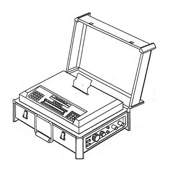
AMI supplied training. THIS MANUAL IS NOT INTENDED AS A SUBSTITUTE FOR THAT TRAINING. The basic Model 207A (M-207A) welding power supply is part of a complete welding system intended for fusion welding of metal tubes, pipes and fittings (see Figure 1). -
Page 8: Safety Precautions
MODEL 207A AND 207A-1 OPERATION MANUAL SECTION I - INTRODUCTION SAFETY PRECAUTIONS This section contains cautions and warnings concerning the operation of this equipment and welding equipment in general. However, in addition to reading this manual and before operating this or any welding equipment, users should reference and be familiar with “ANSI-49.1 Safety in Welding and Cutting”. - Page 9 WARNING: Some systems, are intended solely for in-door use and must be kept dry. Before operating, storing or handling, always make sure that the M-207A, M-207-RP Pendant, weld heads and cables are not exposed to rain or standing water. SYSTEM COMPONENTS ARE NOT WEATHER-PROOF.
-
Page 10: Operational Precautions
If not properly seated or protected, short circuits, poor connections or inert gas leaks could occur. 3. The M-207A is intended for typical GTAW gases ONLY. NEVER CONNECT OXYGEN OR ACETYLENE TO THE M-207A. - Page 11 OR THE M-207A. 10. Do not use acid, corrosives, liquid “Easy Out” or any liquid substance on the M- 207A or any AMI weld head. When cleaning, use only a light solution of Isopropyl alcohol on a soft cloth .
-
Page 12: Shock Hazard Warning
MODEL 207A AND 207A-1 OPERATION MANUAL SECTION I - INTRODUCTION SHOCK HAZARD WARNING As already stated in this manual “High Voltage” is present on exposed internal terminals. The ELECTRODE (tungsten and M-9 rotors) is also an “exposed terminal” and by its nature the GTAW process requires electrical potential to be present on the electrode during arc starting and of course during the welding. -
Page 13: Specifications
11) - Rated No Load Output Voltage (open circuit voltage) is 59 volts for M-207A 79 volts for M-207A-1. 12) - All M-207A models are 100 % Duty Cycle for their rated outputs (9). 15) - Input Voltage type contains symbol for single (1) phase Alternating Current (AC) input at 50 or 60 Hz frequency. - Page 14 IP21 which includes protection against a limited amount of exposure to rain (does not make it weather proof or intended for all weather usage). 22) - All M-207A models are class I. No symbol is used for class I equipment.
-
Page 15: Physical Construction
- 22.75 in (577.9 mm) Depth - 19.25 in (489.0 mm) including handle Weight - 78 lbs (35.4 kg) (M-207A and M-207A-1) PROGRAMMABLE and OPERATIONAL FUNCTIONS PREPURGE TIME ..........= 010 - 999 seconds POSTPURGE TIME ........... = 000 - 999 seconds UPSLOPE TIME .......... -
Page 16: Multi-Level Functions
MODEL 207A AND 207A-1 OPERATION MANUAL SECTION II - SPECIFICATIONS MULTI-LEVEL FUNCTIONS (continued) FUNCTION POSSIBLE CHANGES PRIMARY CURRENT..........= 1 to 99 levels BACKGROUND CURRENT........= 1 to 99 levels PRIMARY PULSE TIME.......... = 1 to 99 levels BACKGROUND PULSE TIME........ = 1 to 99 levels PULSE MODE (ON/OFF)......... -
Page 17: Inspection
Use the following procedure to insure that the M-207A is set-up for the correct AC power. 1. The M-207A is supplied with a 25’ power cord. One end has a connector on it that plugs into the side of the M-207A. The wires on the other end are pig- tailed (no connector). -
Page 18: Welding Gas Connections
The plate is labeled as to what voltage the switch is currently set for. 5. If the M-207A is to be run on 100, 110, 115 or 120 VAC this switch must be in the 110 VAC position. If it is to be run on 200, 208, 220, 230 or 240 VAC it must be in the 220 VAC position. - Page 19 WELDING GAS CONNECTIONS 2. (continued) NOTE The arc gas line is controlled by a solenoid and flow sensor in the M-207A and MUST BE connected to the M-207A (not directly to the weld head or torch). After installing the hose and fittings loosely by hand, tighten the retaining nuts slightly with a wrench to insure there are no leaks, but do not over- tighten.
-
Page 20: Adapter Cable To M-207A Installation
M-207A power supply. 1. One end of the adapter cable ALWAYS connects to the weld head. The other end connects to the M-207A or to a weld head extension cable. The connector types and keyways are different for each item (except gas). -
Page 21: Weld Head Installation
MODEL 207A AND 207A-1 OPERATION MANUAL SECTION III - INSTALLATION WELD HEAD INSTALLATION (continued) 1. Insert the adapter cable GROUND, ELECTRODE AND GAS connectors into the mating weld head cable connectors. 2. After the ELECTRODE, GROUND and GAS connectors are secure and checked, slide the rubber boots on each line together and secure them in place. -
Page 22: System Functions
SECTION IV - SYSTEM FUNCTIONS INTRODUCTION The M-207A is intended for use with AMI orbital welding heads and has functions designed for these weld heads. This section describes what these functions are and may, where needed for clarification, indicate how they are commonly (but not always) used. - Page 23 BACKGROUND PULSE TIMES to set an exact amount of time for each PRIMARY and BACKGROUND function to occur. OVERRIDES - The weld schedule programmer can set the M-207A to allow the operator to change the value of some weld schedule functions. The programmer can also set limits to the amount of changes the operator can make to each function.
-
Page 24: Weld Library And Weld Description
= Indicates the number of times this weld schedule has been used since last reset. WELD SEQUENCE - Although the M-207A can be used as a manual welding power source, it is primarily intended to follow an automatic SEQUENCE. After a weld schedule is selected and the weld is setup, the SEQUENCE will be... -
Page 25: Weld Sequence
MODEL 207A AND 207A-1 OPERATION MANUAL SECTION IV - SYSTEM FUNCTIONS WELD SEQUENCE EVENT 3: LEVEL 1 TIME, START LEVEL, UPSLOPE, TRAVEL. START DELAY - WELD CURRENT UPSLOPE - Sometimes it may be necessary to raise the weld current to full value slowly. This is called UPSLOPE. - Page 26 MODEL 207A AND 207A-1 OPERATION MANUAL SECTION IV - SYSTEM FUNCTIONS WELD SEQUENCE EVENT 4: FULL LEVEL FUNCTIONS - 4. LEVEL 1 BACKGROUND PULSE TIME - If the LEVEL 1 PULSE MODE is ON this function will operate (see Event 3).
- Page 27 MODEL 207A AND 207A-1 OPERATION MANUAL SECTION IV - SYSTEM FUNCTIONS WELD SEQUENCE EVENT 4: FULL LEVEL FUNCTIONS - NOTE Travel direction is programmable CLOCKWISE or COUNTER- CLOCKWISE. After the TRAVEL START DELAY the arc will rotate in the programmed direction. The direction is not programmable by LEVELS.
- Page 28 MODEL 207A AND 207A-1 OPERATION MANUAL SECTION IV - SYSTEM FUNCTIONS PANEL KEYS - The following are descriptions of all active operating keys contained on the system (see figure 6). ALL STOP KEY - Active only during weld sequence in test or weld mode.
-
Page 29: Panel Keys
MODEL 207A AND 207A-1 OPERATION MANUAL SECTION IV - SYSTEM FUNCTIONS PANEL KEYS 11. NUMERIC KEYS - Used to select weld schedule number (#) or to enter numbers during programming, overriding and set-up functions. 12. PREV LEVEL KEY - Same as NEXT LEVEL but levels appear in reverse order. -
Page 30: Operate Mode Switch
SECTION IV - SYSTEM FUNCTIONS PANEL KEYS 21. WELD/TEST KEY - At power on the M-207A will always be in the TEST mode. In TEST mode a weld sequence can be run but NO ARC will be struck. The user must press this key to initiate WELD mode. Once this is done the M-207A will stay in WELD mode as long as the same weld schedule is displayed. -
Page 31: Faults
FAULTS The M-207A has the ability to monitor certain functions. If they are not working correctly a system fault (FLT) will alert the operator to the problem. The following is a description of each type of fault (FLT): TEMP FLT - Power supply internal TEMPERATURE IS TOO HIGH. -
Page 32: Sensor 1,2,3 Faults
SENSOR 1, 2, 3 FAULTS The M-207A has 3 separate inputs that the user can define for creating a fault condition based on some external problem. The most common would be connecting a gas analyzer (s) to the M-207A to detect excessive Oxygen in the I.D. - Page 33 15. OPERATOR ID/NAME - Used to enter the ID number or name of the weld operator. 16. SERIAL NUMBER - Used to enter the M-207A Serial Number for Weld Data Record feature. 4.14 Doc. No. 740044...
- Page 34 MODEL 207A AND 207A-1 OPERATION MANUAL SECTION IV - SYSTEM FUNCTIONS GLOSSARY OF DISPLAY SYMBOLS AND ABBREVIATIONS - The M-207A displays contain many abbreviations. The following is an alphabetical listing (symbols last) of most abbreviations. = Aluminum = Amperage = Automatic weld fitting = Background (low value of a function that pulses).
-
Page 35: Glossary Of Abbreviations
= Weld schedule number = Indicates that more information is available 4.10 GLOSSARY OF DISPLAY TERMS - The M-207A displays contain many terms that do not relate directly to a function or sequence. The following is a listing of those terms:... - Page 36 SENSOR 1, 2, 3 = User defined faults. STORE = Puts weld information into memory. TRANSFER = Allows copying of memory to another M-207A or to the M-207-EMM. TYPE = Describes the basic type of weld. WALL = Wall thickness of the weld.
-
Page 37: Introduction
3.1 have been complied with. WARNING Applying the wrong input AC voltage to an M-207A (for how it is set up) CAN CAUSE THE INPUT VARISTORS TO FAIL. Before turning the power ON MAKE SURE THE INPUT POWER SET UP IS CORRECT FOR THE POWER BEING USED. -
Page 38: Use Of Next/Prev
If the input power is too low it is possible for the screens not to turn on, or to be scrambled or get a fault screen indicating a LVPS fault. If these conditions occur recycle CB1. If they continue to occur check the input power and the power setup of the M-207A UPPER SCREEN TO WELD PRESS LIB TO PROGRAM PRESS PRO SYS HOURS - 00000.0... -
Page 39: Weld Schedule Selection
MODEL 207A AND 207A-1 OPERATION MANUAL SECTION V - OPERATION USE OF NEXT/PREV SCREENS/LEVELS (continued) The weld schedule can be programmed to have up to a 100 levels of screen 2 and 3. When viewing screen 2 or 3 the operator can press the NEXT LEVEL key to view the values for the next level (if programmed). -
Page 40: Viewing Function Values
MODEL 207A AND 207A-1 OPERATION MANUAL SECTION V - OPERATION WELD SCHEDULE SELECTION 4. To find the weld schedule you want press the NEXT SCREEN key. The next weld schedule in memory will be displayed. Continue pressing the NEXT SCREEN key until the desired weld schedule appears. When the desired schedule appears, press the ENTER key. -
Page 41: Overriding Function Values Before Seq
3. Press the SEQ START key to run this weld sequence. (See 5.9 OVERRIDING FUNCTION VALUES, BEFORE SEQUENCE START Each weld schedule in the M-207A library can be programmed to allow unlimited, limited or NO changes to be made to the function values of the weld schedule. If the weld schedule allows changes to be made use the following procedure. -
Page 42: Set Up Functions
NOTE The SET UP screens offer special functions that can ENHANCE or in some cases CHANGE the way the M-207A operates. It is important for the user to understand these features. Under some conditions, if not properly set, undesirable performance can occur. - Page 43 MODEL 207A AND 207A-1 OPERATION MANUAL SECTION V - OPERATION SET UP FUNCTIONS 1. SET UP FUNCTIONS IN OPERATE MODE HEAD CAL - This feature is used to calibrate Travel (rotation) speed of the Weld Heads and MUST BE USED ANY TIME A CHANGE OF WELD HEADS IS MADE.
- Page 44 MODEL 207A AND 207A-1 OPERATION MANUAL SECTION V - OPERATION SET UP FUNCTIONS 1. SET UP FUNCTIONS IN OPERATE MODE 8. WELD DATA RECORDING (WDR) - Selecting this feature will access another screen that will allow the user to turn on WDR and/or turn on WELD ID recording.
- Page 45 High and Low. 3. PRINTER MODE - The M-207A can be set up to make a print out of the Weld # automatically (AUTO) after every Sequence. If set to MANUAL a print will only be made if the PRINT key is pressed after a weld sequence.
-
Page 46: Auto Rotation Calibration
5. DATE RESET - Prints contain the DATE of print. The DATE can be RESET by using this feature. 6. QTY - RESET - The M-207A keeps count of how many times an individual WELD # is successfully run. It also TOTALS this count for the entire LIBRARY. - Page 47 PRESS ENTER TO START CALIBRATION USE C KEY TO RETURN TO SET UP SCREEN 4. When the ENTER key is pressed the M-207A will proceed to move the rotor automatically and calibrate it. MAKE SURE IT IS SAFE TO ROTATE BEFORE STARTING.
-
Page 48: Manual Rotation Calibration
MODEL 207A AND 207A-1 OPERATION MANUAL SECTION V - OPERATION AUTO ROTATION CALIBRATION 7. For operation on other systems and MANUAL calibration all AMI weld heads have a Calibration Potentiometer. An exact setting of this POT is not required for AUTO CAL but if it is set near one end the system may not be able to accurately calibrate. - Page 49 MODEL 207A AND 207A-1 OPERATION MANUAL SECTION V - OPERATION MANUAL ROTATION CALIBRATION 2. Press the F key under MANUAL. The screen will return to the first SET UP screen and the system is now set for MANUAL calibration. Press the C key to return to the STATUS screen.
-
Page 50: Welding Operation
WELDING OPERATION NOTE Before running a weld schedule the weld head must be calibrated to the M-207A. When a weld head is switched from one power supply to another it must be re- calibrated to the new power supply. If the weld head being used has not been calibrated, perform the calibration procedure per step 5.8 or 5.9. -
Page 51: Printer Operation
1. The printer receives its power form the M-207A and does not require any external manipulations (other than installing the paper roll). 3. The printer is activated by using the PRINT key on the M-207A panel or the PRINT key on the M-207-RP remote pendant. The PRINT keys will only activate the printer under the conditions of step 4. - Page 52 MODEL 207A AND 207A-1 OPERATION MANUAL SECTION V - OPERATION 5.11 PRINTER OPERATION 4. (continued) 2. LIBRARY SCREEN - When the LIB key is pressed and any of the library screens are being displayed a copy of the description of ALL WELD SCHEDULES in memory can be printed.
-
Page 53: Introduction
MEMORY IS ALSO A FEATURE OF THE MODE. This section explains very basic operation of each of these programming functions. For the most part the M-207A is self teaching because of the instructions on the screen for each type of function; only general information is given in this section. - Page 54 NOTE Use of the C key - Anytime during programming the entire process can be stopped by pressing the C key. If this is done the M-207A will ask the programmer to confirm that cancellation of the programming sequence is desired.
- Page 55 5. After pressing the ENTER key follow the instructions on the screen for entering the WALL thickness. 6. The M-207A will then give you a choice of 8 TYPES of welds. Use the F keys to pick the type and then press ENTER. Then use the same method for MAT (material).
-
Page 56: Modify A Weld Schedule
MODEL 207A AND 207A-1 OPERATION MANUAL SECTION VI - PROGRAMMING CREATE A WELD SCHEDULE 9. When the PRO key has been pressed, indicating the end of level programming, the system will display the OVERRIDE screen: USE F KEYS TO SELECT ITEM - %... -
Page 57: Copy A Weld Schedule
MODEL 207A AND 207A-1 OPERATION MANUAL SECTION VI - PROGRAMMING MODIFY A WELD SCHEDULE 2. Modifying a weld schedule works similar to reviewing a weld schedule in the operate mode (see section V). Use the NEXT/PREV SCREEN and NEXT/PREV LEVEL keys to find the function and level to be modified. -
Page 58: Transfer/Receive A Weld Schedule
5.6.2 about the LOCK, UNLOCK feature of Weld #’s 71 to 100. If a user has more than one M-207A, it is usually a good idea to keep both libraries identical. This is done by TRANSFERRING a COPY of the LIBRARY of one system into the M-207-EMM;... -
Page 59: Delete A Weld Schedule
Individual weld schedules CANNOT be added one at a time to the M-207- EMM from the M-207A (TRANSFER mode). Individual weld schedules CAN BE added one at a time to the M-207A from the M-207-EMM (RECEIVE mode). See section 8.3 for more cautions. -
Page 60: Introduction
Except for the Current Servo all system functions are controlled by the processor and no calibration points or steps are required. Rotation calibration is contained in section 5 and is automatically done by the M-207A. It can be verified by a physical count of rotation versus time if required. - Page 61 OPERATION MANUAL SECTION VII - CALIBRATION CURRENT CALIBRATION The M-207A contains components for measuring the actual amount of current. Normal calibration is intended for adjusting the circuitry based on measuring these devices. True verification of current output for Quality Control purposes must be done with an External Calibration Shunt that is calibrated by an independent agency and controlled by a users QC or QA department.
- Page 62 Head Adapter Cable or manual torch cable. Current is always measured along the ground return path. 5. Insure everything is ready to strike an arc. Turn M-207A power ON. The system should return to your calibration weld procedure. Set the Weld/Test Mode to WELD.
- Page 63 MODEL 207A AND 207A-1 OPERATION MANUAL SECTION VII - CALIBRATION CURRENT CALIBRATION 9. DO NOT INSERT THE PROBES UNTIL AFTER THE ARC IS STRUCK. The high frequency start may damage some meters. 10. Press the SEQ START key. 11. As soon as the arc is struck (after prepurge) insert the Probes into the center plate test points or into the external shunt if it is being used.
-
Page 64: General Maintenance
Always disconnect the AC power cable from the line voltage before attempting to work with this welding power supply. AIR FILTER - The M-207A power supply has one (1) foam air filter. Inspect this air filter regularly. The foam filter may be washed in water and detergent, dried and reused or replaced. -
Page 65: System Fault Corrections
This fault could occur if a weld schedule is asking for 110 amperes or more and the M-207A is being operated on 120 VAC. The M-207A can only supply over 100 amperes when operated on 200 VAC or higher. - Page 66 MODEL 207A AND 207A-1 OPERATION MANUAL SECTION VII - CALIBRATION SYSTEM FAULT CORRECTIONS GAS - This fault will only occur at the beginning of or during a Weld Sequence. If the arc gas flow through the system should stop, or be to low, a fault will occur.
- Page 67 These conditions tend to create very high Arc Voltages and could cause an undesirable FAULT if this option is left ON. BAD START - If for any reason the M-207A cannot achieve a stable Arc at the end of PREPURGE the system will display this statement.
-
Page 68: Error Messages
Voltage. Another possible reason for no display or scrambled displays is RF interference. Although the M-207A is protected against this certain conditions are still possible to occur that can cause this. Outside RF from another type of source such as a HF welding machine or a radio transmitter near by could cause a problem. -
Page 69: Miscellaneous Maintenance Items
MODEL 207A AND 207A-1 OPERATION MANUAL SECTION VII - CALIBRATION ERROR MESSAGES MEMORY CHECK (continued) NOTE When the print key is pressed any weld schedule with a directory or link error will automatically be “DELETED”. Any schedule with a sum check error will be flagged corrupted on the print out and the user should call up that weld schedule and verify the parameter values. - Page 70 Manual (#740078). RS232 COMMUNICATIONS The M-207A can shut down the RS232 port on it own if it detects non-intelligent information on it. This can be caused by ambient light or improper set up. The RS232 port will not be re-activated until the power has been re-set.
-
Page 71: Introduction
60 PSI, and flow rate FAULT detect switches. Installation 1. Insure that the M-207A is OFF, remove the power cable from the M-207A and set the CW ON/OFF switch to the OFF position (see figure 8). 2. The cooling unit is shipped dry and requires 3 gallons (11.4 liters) of CLEAN DISTILLED or DE-IONIZED water. - Page 72 CW Power Cable location and find the location of the mating connector on the bottom of the M-207A. 4. Move the M-207A onto the CW unit and insert the corners onto the posts of the CW Unit. Carefully tilt the front of the M-207A up slightly. With...
-
Page 73: M-207-Rp Remote Pendant
2. Both M227/207-CW & M207-CW contain flow sensors. Any time the CW unit is turned ON a signal will be sent to the M-207A that indicates if the flow is adequate If it is the M-207 STATUS screen (at power up) displays COOL-OK. - Page 74 11. Amps Up key 12. Amps Down key 2. Items 1 to 8 above are duplicates of keys contained on the M-207A panel. They work exactly the same as the keys on the panel. When the RP is connected these keys and the identical ones on the M-207A panel are active at the same times.
- Page 75 M-207-RP REMOTE PENDANT Operation (continued) 4. As previously noted, the M-207A can store in memory up to 100 weld schedules. Any 4 of these schedules can be programmed to be selected from the RP. The Weld # key is used to select one of these 4 weld schedules.
-
Page 76: M-207-Emm External Memory Module
This connector should be inserted into the slot on the side of the M-207A labeled EMM. It is keyed and can only be inserted one way. When installed, turn the M-207A ON and perform the desired TRANSFER or RECEIVE functions as described in Section VI of this manual. - Page 77 MODEL 207A AND 207A-1 OPERATION MANUAL Doc. No. 740044 Rev F...
Need help?
Do you have a question about the 207A and is the answer not in the manual?
Questions and answers