Advertisement
Quick Links
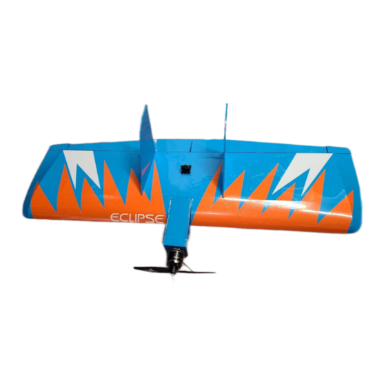
Eclipse Build Manual
Thank-you for your purchase of the new Eclipse kit, the following instructions are meant
to guide you in assembling your plane.
Advanced builders may find they need to make slight deviations in order to better suite
their abilities and desired plane outcome.
As always due to the type of wood used slight bends or warping to the wood may occur
but should not affect the overall stru cture.
**This manual contains instructions for both electric and glow type builds. **
Page | 1
©Direct Connection RC
Advertisement

Related Manuals for Direct Connection RC Eclipse

Summary of Contents for Direct Connection RC Eclipse
- Page 1 Eclipse Build Manual Thank-you for your purchase of the new Eclipse kit, the following instructions are meant to guide you in assembling your plane. Advanced builders may find they need to make slight deviations in order to better suite their abilities and desired plane outcome.
-
Page 2: Additional Requirements
8x8 APC electric prop or a 9x6 Glow rated prop • Glow Use - 120CC tank; 3 ½” x 2” x 1 ½” • 256 push rods with steel clevises and fuel line to hold the clevises closed. • Dubro control surface horns Page | 2 ©Direct Connection RC... - Page 3 Glue together the two main spar pieces at the zig-zag joint using your preferred glue (CA); allow to set. Set aside. Page | 3 ©Direct Connection RC...
- Page 4 3. Assemble the 3 pieces of the battery cover. Glue and allow to set. Set aside. 4. Ensure you have a complete rib set with 2 ribs numbered 1 through 7. Page | 4 ©Direct Connection RC...
- Page 5 1. Place the fuselage bottom on a flat surface. Identify the left (top circle; longer tab) and right (bottom circle; shorter tab) sides of the fuselage; a thrust angle is built into the fuselage. Page | 5 ©Direct Connection RC...
- Page 6 NOT required, and may be discarded. All the F1 former tabs should fit snugly inside the fuselage. Glue the front tabs of the fuselage and the F1 former at this time. Leaving the back portion of the fuselage open at this time. Page | 6 ©Direct Connection RC...
- Page 7 You can run the throttle servo linkage through the center fuse former and drill your hole in the firewall as required for your engine throttle linkage. Page | 7 ©Direct Connection RC...
- Page 8 We recommend using foam around the fuel tank and some kind of strap epoxied to the fuselage to hold the fuel tank in place and all other necessary items. Page | 8 ©Direct Connection RC...
- Page 9 You may wish to take this time to install your blind nuts. You may also wish to brush coat a thin layer of epoxy on the inside of the fuselage to protect the wood from fuel leaks. Page | 9 ©Direct Connection RC...
- Page 10 6. Install the top motor box cover onto the fuselage. We recommend Epoxy. 7. Glue in the rear servo mount tray onto the rear back portion of the fuselage. Page | 10 ©Direct Connection RC...
- Page 11 Fuselage should be sanded to allow for covering to adhere later on. Set the fuselage aside. 9. Set the main spar up on edge with the slots facing up, ensuring the longest edge of the zig zag joint is on the left-hand side as shown. Page | 11 ©Direct Connection RC...
- Page 12 10. Set the main spar brace onto the front of the wing overlapping the zig zag joint before placing the ribs into the main spar. Page | 12 ©Direct Connection RC...
- Page 13 #1 out to the edge to ribs #7 on each side. (The 3 rib is a half rib and is tucked beside Rib 2 making the numeric non visible in the photo.) Page | 13 ©Direct Connection RC...
- Page 14 3 pieced zig zag joint aligning to the left matching the main spar. Tips* Wax paper or Parchment paper before you pin the wing down Page | 14 ©Direct Connection RC...
- Page 15 Square the bottom trailing edge to the ribs and pin as necessary. 15. Once everything has been squared and fitment is snug glue each rib (less the half rib at this time) with CA. Pressing each rib firmly into place while gluing. Page | 15 ©Direct Connection RC...
- Page 16 Then insert the top trailing edge piece working from the center outwards to adhere to the ribs and trailing spacers. You may require weights or additional pins to hold the top trailing edge in place while the glue sets. Page | 16 ©Direct Connection RC...
- Page 17 If building for a higher torqued plane than specified a piece of 1” fiberglass cloth may be wrapped around the main spar joint to provide additional strength, in extreme circumstances. 21. Re-pin the plane to your building board. Page | 17 ©Direct Connection RC...
- Page 18 Allow to set. Note Ribs #5 - #7 23. Unpin the plane from the building board. Turning the plane over glue the backside of the ribs to the main spar using wood or white glue. Page | 18 ©Direct Connection RC...
- Page 19 24. Test fit the fuselage to the wing. The fuselage cutouts along the sides should align with the main ribs. You may be required to sand the fuselage again. 25. Place the supplied wing tips into the main spar ends, ensure wing tips are sitting flush before gluing into place. Page | 19 ©Direct Connection RC...
- Page 20 29. Repeat for both sides of the leading edge; top and bottom of the ribs. 30. Sand the inside pieces of the leading edge where the fuselage will sit. Page | 20 ©Direct Connection RC...
- Page 21 32. Sand and prep the sheeting before gluing the sheeting onto the wing. *Placement for sheeting is shown in step 34. 33. Glue the left and right center wing sheeting pieces together as shown: Page | 21 ©Direct Connection RC...
- Page 22 Recommended using CA or wood glue to adhere, weights may be required to affix the sheeting. 36. Repeat step 35 for the bottom sheeting. Remember this sheeting is only 3” wide compared to the top sheeting at 3 ⅛” wide. Page | 22 ©Direct Connection RC...
- Page 23 40. Locate the elevons, along the long flat edge cut or sand to a 45°. Shape the elevons as desired. Round the aft edges of the elevons. You may want to sand your elevons to match the trailing edge wing tips and shape at the same time. Set aside for covering. Page | 23 ©Direct Connection RC...
- Page 24 42. The tension can be adjusted by sanding the notches by the motor mount on the battery cover; see photo. The tension will be set individually depending on how you want to hold the battery cover in place. Page | 24 ©Direct Connection RC...
- Page 25 46. Add decals as desired. We provide two orange and two white finishing decals along with the Eclipse logo. Decals can be difficult for even an experienced builder we recommend using transfer tape to apply our decals and where possible an extra set of hands.
Need help?
Do you have a question about the Eclipse and is the answer not in the manual?
Questions and answers