
Related Manuals for Biorep Technologies PERI-4.2

Summary of Contents for Biorep Technologies PERI-4.2
- Page 1 PERIFUSION SYSTEM MODEL No: PERI-4.2 ______________________________________________________ USER MANUAL ______________________________________________________...
-
Page 2: Table Of Contents
© BIOREP 2016 (r10-22) TABLE OF CONTENTS GETTING STARTED ................................. 3 ................................3 YMBOLS SED IN THIS ANUAL ..................................3 ACHINE NFORMATION ..................................3 ONTACT NFORMATION .................................... 4 AFETY NFORMATION ....................................5 REPARATION ......................................5 ACKING INTRODUCTION ..................................6 MACHINE PARTS IDENTIFICATION ..........................7 ACCESSORIES .................................... -
Page 3: Getting Started
In the spaces provided below, record the Model and Serial No. located on the rear panel of your machine. Model No. __________________ Serial No.______________________ RETAIN THIS INFORMATION FOR FUTURE REFERENCE. Contact Information Biorep Technologies, Inc. 15804 NW 57 Avenue Miami Lakes, FL 33014 info@biorep.com www.biorep.com... -
Page 4: Safety Information
If the provided plug does not fit into your outlet, consult an electrician for replacement of the obsolete outlet or contact Biorep Technologies, Inc. at (305) 330-4449. 4. Protect the power cord, the power entry module, and the plug from being walked on or pinched to avoid damaging them. -
Page 5: Site Preparation
Site Preparation This machine is intended to work in a controlled laboratory environment. In order to properly place the machine, please refer to the figure below. The machine has a ventilation opening in the rear, which should not be blocked. A 12.7cm (5.0 in) clearance is recommended between the back of the machine and any obstacle. -
Page 6: Introduction
Introduction Congratulations on your purchase of the Biorep Perifusion system. This is the newest generation of a product that has received countless hours of development to include all the features necessary to perform the most controlled and precise stimulated cell secretion experiments in the field. You will not be disappointed with the value and efficiency this machine will bring to your research. -
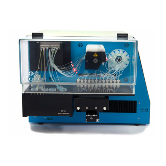
Page 7: Machine Parts Identification
Machine parts identification Figure 3: Perifusion system, side view Figure 4: Perifusion system, front view... - Page 8 Figure 5: Perifusion system, back view 1. Removable source holder 2. 32 (8 x 4) valve manifold for source handling 3. 12 Channel peristaltic pump (Main pump) 4. Temperature control inlet/outlets (x6) 5. Perifusion chamber 6. Sample collection tray 7. Alarm buzzer 8.
-
Page 9: Accessories
Accessories A complete set of accessories is included with the machine. For ordering additional or replacement accessories please consult our webpage www.biorep.com or contact one of our sales representatives at (305) 330-4449. Tubing Set The Perifusion tubing set delivers the stimulus to the cell chamber while minimizing dead volume. The perifusion tubing set is made out of 2 types of tubing: A- Connection tubing, which is for the perifusion fluid handling system (source-manifold, manifold-pump, pump-chamber);... -
Page 10: Perifusion Chamber Auxiliary Rack
Perifusion chamber auxiliary rack The auxiliary rack is included with every Perifusion system to assist in the preparation of the Perifusion chambers. The rack can hold up to 8 chambers at a time for cell loading outside the machine. This allows the scientist to do the preparation away from the machine in a more comfortable position. -
Page 11: Perifusion System Overview
A fiberglass filter sheet is included with every perifusion system. A hole puncher (included) is used to make round cut-outs of the filter sheet to place inside the perifusion chamber during its set-up. The purpose of this filter is to retain the chamber contents while allowing the flow of the perfusate. -
Page 12: Valve Manifold
6. COLLECTION: The perfusate is collected in a well plate for further analysis. The collection tray moves automatically accordingly to the number of active columns (Perifusion chambers) and the pre-set sampling rate. The collection tray can hold deep and standard 96 well plates; be sure to place the included spacer adapter inside the tray to use it with standard plates. - Page 13 Manifold states are represented by the letter and number combination “CHANNEL-SOURCE” for each of the four channels: An, Bn, Cn, Dn, where n = 0-8, depending on the selected source (“0” represents a closed channel). Example: The manifold state: A2, B3, C8, D0, means output A will be from source 2, output B will be from source 3, output C from source 8 and the outputs of channel D is Inactive/closed.
-
Page 14: Peristaltic Pump
Peristaltic pump The sources are pumped from their containers through the open valves of the manifold by the main pump. The main pump is a 12 roller, high precision peristaltic pump, capable of handling up to 12 channels simultaneously, providing accurate and identical dispensing across channels. Figure 14: Peristaltic Pump (Only 8 channels shown) The main body of the pump (1), is fixed to the machine chassis. -
Page 15: Collection Tray
Figure 15: Perifusion Chamber and collection tube Collection tray Figure16: Collection Tray The collection tray (1) holds and positions the well-plate (2) for automated collection of the perfusate and cell secretions according to programmed time intervals. The collection tray can be used in a Horizontal or Vertical configuration with respect to the positioning mechanism (3). -
Page 16: Perifusion System Basics
Perifusion System Basics Control and operation of the Perifusion system is done through the touch-screen interface. This type of interface eliminates the need for an external keyboard or mouse device and provides a visual and intuitive interaction with the user. The operator should familiarize himself/herself with the different screens, features, and controls of the interface before attempting to operate the machine during an actual perifusion. -
Page 17: Logging In
Logging In The Login Page allows you to Log into your password protected user account. The user account saves your protocols, reports, and the preferences of your experiments; it also saves time by pre-filling some frequently used fields during the experiment process and during reporting. -
Page 18: Main Menu
Main Menu Figure 20: Main Menu Once logged in, you will arrive at the Main Menu page. On this page you can start an experiment, via the “Protocol Wizard”; configure the settings of the machine, or manually control the different sub-systems of the machine via the “Test Page”. -
Page 19: Test Page
Test Page Figure 21: Test Page The best way to get acquainted with the different sub-systems of the Perifusion machine is by playing around in the Test Page. You can test the alarm buzzer by pressing the “Test Buzzer” button, or confirm the proper sensing of the tray orientation by looking at the icon on the top right. - Page 20 TEMPERATURE: The temperature systems can be tested by these controls. The “HEATER” button enables the heater and the convection fans. The incubator PV (Present Value) will be displayed below. The tray cooling pump can be turned on by pressing the “Tray Pump” button.
-
Page 21: Settings
Settings Figure 26: Settings page Before starting your perifusion experiments you have the option of customizing parameters relating to the temperature alarms, tray handling and protocol execution timing. ALARMS: The alarms are listed in the left hand side of the page. They can be de-activated in case of a special case need, where a particular alarm is bothersome, but it is recommended that all alarms remain active for protection of the machine. -
Page 22: Perifusion Operation (Protocol Wizard)
Perifusion Operation (Protocol Wizard) Continuing our effort to make Perifusion experiments more streamlined, and reduce the chance of error during setup, we have developed a “Wizard” type interface to set-up and run your experiments. The wizard will guide you step by step through the setup of the machine, setup of the sample, execution of your protocol, reporting of the results, and even post-experiment maintenance of the machine. -
Page 23: System Setup
Figure 28: Protocol page This means that a step with Rep# = 5 and Time = 20secs will dispense the selected solutions for 20 seconds, then move the collection tray to the next row of wells and dispense the same solutions for another 20 seconds, and so on for 5 consecutive well rows. -
Page 24: Chamber Setup
Some of these steps may be overlapping. Please read the entire setup instructions carefully before attempting to do it on your machine. For further assistance please contact customer support. Chamber Setup Prepare the perifusion chambers as shown in the wizard screen: 1. -
Page 25: Priming
1. The tubing (5) is inserted in the cassette (6a) by sliding it through the groove. 2. The orange colored detent (5a) on the manifold side should mate with the notch in the back of the cassette. 3. The tubing should be longer on the chamber side than on the manifold side 4. -
Page 26: Chamber Positioning
Chamber positioning Care must be taken when positioning the perifusion chambers on the perifusion chamber rack inside the incubator. Chamber placement starts from the right-most position with the last chamber, and then subsequently filling positions to the left until the first chamber is placed. The first chamber should be the leftmost chamber. This is of critical importance to the proper functioning of the experiments;... -
Page 27: 7.10 Protocol Execution
Cooling 1. To set up the tray cooling, fill a container with coolant. The coolant can be chilled water or a mixture of water and alcohol 2. Connect 1/8" I.D. silicone tubing as shown on the figure 3. Prime the diaphragm pump using a siphon or syringe 4. - Page 28 Figure 36: Protocol monitor The Monitor screen can be divided in 5 functional sections: EXECUTION CONTROLS These controls allow you to START, PAUSE and STOP the protocol execution at any time. Starting the execution of a protocol requires two steps. The first time you press the PLAY button, the machine will “HOME”. This will allow you to load a 96 well plate into the sample tray.
-
Page 29: 7.11 Protocol Examples
TEMPERATURE These controls allow you to control and monitor the temperature settings of the system. The HEATER button controls the incubator heater. The current incubator temperature is displayed on the Incubator PV (Present Value) indicator. The TRAY PUMP button controls the cooling pump for the sample tray. The tray temperature is displayed on the Tray PV indicator. - Page 30 AUC= Area Under Curve...
-
Page 31: Finalizing The Experiment
Finalizing the Experiment Collecting the cells 1. Top cap 2. O-ring 3. Cell chamber 4. Fiberglass filter 5. Bottom cap 6. Micro-centrifuge tube Figure 42: Perifusion Chamber and collection tube 1. Disconnect the tubing attached to the bottom cap of the chamber. 2. -
Page 32: Cleaning The System
Cleaning the system After the protocol has been executed successfully, the system must be thoroughly cleaned, not only to ensure your system lasts longer, but most importantly, to eliminate all residues from the fluidic system, that may cause the system to malfunction, or inadvertently affect the results of future experiments. The wizard includes a cleaning step to help you do this in the most effective manner. -
Page 33: 10 Customer Service
STEP. This map is useful when cross-referencing the data to subsequent processing such as ELISA. 10 Customer Service If you encounter any problems, please contact customer support at: Biorep Technologies, Inc. 15804 NW 57 Miami Lakes, FL 33014 info@biorep.com www.biorep.com... - Page 34 APPENDIX A Buffer Preparation Buffer Solvent: De-ionized water (ddH2O) Buffer Solute Ingredients/ Proportions: To prepare 200ml of KRB. (prepare right before use) 1. Add 20ml of Solution 1 to 100ml of ddH2O 2. Bubble gently with 95% O2/5% CO2 for 10 minutes 3.
- Page 35 Bead Suspension Preparation Add beads to 5ml mark of a 50ml conical Add 40ml of buffer solution. Prepare bead-buffer suspension at least one day before the experiment to allow beads to absorb buffer. Keep the bead-buffer suspension refrigerated (4℃) ...
Need help?
Do you have a question about the PERI-4.2 and is the answer not in the manual?
Questions and answers