Table of Contents
Advertisement
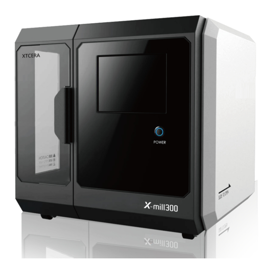
X-MILL 300
:Shenzhen Xiangtong Co.,Ltd
Address: 2F,1Building,Honghualing west Industrial Park,88th zhuguang
north road,xili,Nanshan District,ShenZhen,Guangdong,China
Tel: 0086 755 8600 1804
Fax: 0086 755 8600 1486
E-mail: xtcera@xianton.com
http://en.xtcera.com
300
User Manual
X-MILL 300 Four-axis Engraving & Milling Machine
Advertisement
Table of Contents

Related Manuals for XTCERA X-MILL 300

Summary of Contents for XTCERA X-MILL 300
- Page 1 X-MILL 300 User Manual X-MILL 300 Four-axis Engraving & Milling Machine :Shenzhen Xiangtong Co.,Ltd Address: 2F,1Building,Honghualing west Industrial Park,88th zhuguang north road,xili,Nanshan District,ShenZhen,Guangdong,China Tel: 0086 755 8600 1804 Fax: 0086 755 8600 1486 E-mail: xtcera@xianton.com http://en.xtcera.com...
-
Page 2: Table Of Contents
FOREWORD Preface Dear customers, Chapter 1 Introduction to X-mill 300 Four-axis Engraving & Milling Machine 1 Thank you for choosing the products of Xiangtong. Xiangtong X-mill 300 series 1-1 Product Introduction four-axis engraving & milling machine is a precise device created by the company. -
Page 3: Chapter 1 Introduction To X-Mill 300 Four-Axis Engraving & Milling Machine
1-1 PRODUCT OVERVIEW 1-2 OUTLINE STRUCTURE X-mill 300 Four-axis Engraving & Milling Machine is an integrated engraving and milling machine featuring high precision, high efficiency and high integration, and it can be used for processing Zirconium oxide/wax/PMMA/Premilled abutment base/glass ceramic. The machine adopts horizontal structure. -
Page 4: Main Structure
1-3 MAIN STRUCTURE Dimension (L*W*H):730*720*620(mm) Input voltage:AC220V X-mill 300 4-axis engraving and milling machine is mainly composed of engine base, Spindle power:1.8KW XYZ:125/130/80mm A:360° linear motion mechanism, motor drive system, motion control system, circuit-pneumat- (±20° .positioning processing) Travel range: ic-water control system, man-machine operating interface and shell body. -
Page 5: Notes For Equipment Installation
CHAPTER 2 INSTALLATION AND COMMISSION 2-2 EQUIPMENT DEBUGGING 2-1 NOTES FOR EQUIPMENT INSTALLATION 1.Turn on the equipment power switch,then the lights in the processing areas will be lighted up and the system will start. 1. Open the packing case and check if the equipment appearance is damaged. 2. -
Page 6: Chapter 3 Commissioning And Processing
8. Click the “FIRST REFERENCE” button and the “SECOND REFERENCE” button suc- cessively and observe if the equipment movement is normal and if the equipment stop posi- tion is correct. 7. T1~T6 buttons highlight indicates current system bur number. Observe if the bur number on the spindle collet is the same as that displays in the system;... - Page 7 3-2 PROCESSING AND RUNNING 1. After completing the commissioning operation, formal production can be started. The operation steps of formal production are basically same as the commissioning operation steps. 2. In manual mode, click the "FIRST REFERENCE" button and the axes will automatically return to a position suitable for loading and unloading material plate.
-
Page 8: Key Points For Circular Material Clamping
3-3 MILLING BUR SELECTION AND REPLACEMENT 5. Insert the new bur into the spindle collet, make sure the lantern ring reached to the 3-3 BUR SELECTION AND REPLACEMENT collet and then tighten the collet by click the collet button agian in the manual interface. Using lantern ring is to make sure that bur installation depth conforms to the equipment Bur replacement, which is very important in daily processing, will directly affect equipment safety and quality and thus needs careful operation. -
Page 9: Abnormality Elimination
3-6 Abnormity Elimination 3. There should be no residue on edge of the re-clamped material, which must be cleaned to prevent fracture caused by uneven force when clamping. There are system information tips on the automatic interface. Under normal circumstanc- 4. -
Page 10: Maintenance
CHAPTER 4 MAINTENANCE AND MATTERS 4-2 SPECIAL ANNOUNCEMENT: NEED ATTENTION 1. If you purchase equipment of our company, using for processing other products than specified materials in this manual, please make good evaluation according to the above 4-1 MAINTENANCE INSTRUCTIONS: equipment parameters. -
Page 11: Chapter 5 Common Abnormalities And Countermeasures
CHAPTER 5 COMMON ABNORMALITIES AND COUNTERMEASURES 4.Spindle cooling water must be added with anti-rust agent to prevent rust congestion; and regularly check of water yield must be made according to the requirements of regulations. Contact us for anti-rust agent specifications. Fault phenomenon Reason analysis Countermeasures... -
Page 12: Appendix I Equipment Overall Operation Flow Chart
APPENDIX I EQUIPMENT OVERALL OPERATION FLOW CHART Connect the power cord Turn on the power switch and the system is powered on System starting completed Waiting for starting completed Run software and perform processing operations Equipment using completed Continue to use Exit the software and close Windows with normal operation Normal close completed Waiting for closing completed...
Need help?
Do you have a question about the X-MILL 300 and is the answer not in the manual?
Questions and answers
При загрузке стратегии появляется ошибка на станке M11, Line 4966 = 21