
Related Manuals for RDA FirePro V2

Summary of Contents for RDA FirePro V2
- Page 1 Manual (Translated) FirePro V2 Control Unit Door control for FS drives: FirePro V2 Control Hardware version V2. 3 Software version V4.1 Publication Date: 02/12/2021...
- Page 2 Door control FireProV2 Manual Please keep this manual with attachments carefully!
- Page 3 Door control FireProV2 Manual 1 Index: Index: ..........................2 Safety instructions ......................4 Relevant Safety requirements: ................4 Control Print Overview ....................5 Schedule with NES motor ..................... 6 Schedule with DES motor ..................... 7 Technical data ....................... 8 Description of Control Unit ................... 9 Fire alarm: ......................
- Page 4 Door control FireProV2 Manual 10.9 Continuing when empty or disconnected battery: ..........29 10.10 Opening after passing digital limit switches ............ 29 10.11 Low battery voltage ..................29 10.12 Notifications ..................... 29 10.13 Maintenance counter ..................30 Menu ........................31 11.1 Parameter settings 0.
-
Page 5: Safety Instructions
Door control FireProV2 Manual 2 Safety instructions This manual is translated from the original Dutch manual, In the event of discrepancies between the two, the Dutch version shall prevail. Read this manual carefully before starting work on this Control unit. Check the screw connections before this control unit becomes operational. Caution: before starting work on this control, first Disconnected the power supply and disconnect the poles of the batteries. - Page 6 Door control FireProV2 Manual 3 Control Print Overview Please keep this manual with attachments carefully!
- Page 7 Door control FireProV2 Manual 4 Schedule with NES motor Please keep this manual with attachments carefully!
- Page 8 Door control FireProV2 Manual 5 Schedule with DES motor Please keep this manual with attachments carefully!
-
Page 9: Technical Data
Door control FireProV2 Manual 6 Technical data Power supply : 3N ~ 400VAC +/-10%, 50/60Hz : 3 ~ 230VAC +/- 10%, 50/60Hz : 1N ~ 230VAC +/-10%, 50/60Hz Fuse : Max. 5A Slow Maximum power : 2,2Kw Maximum current : 8,5A Control voltage : 24Vdc Control current... -
Page 10: Fire Alarm
Door control FireProV2 Manual 7 Description of Control Unit The FirePro is a controller for failsafe drives (FS series) with mechanically adjustable limit switches (NES) or digital Absolute Encoder (DES) and centrifugal brake. This control unit can work both automatically and in hold to run. The operation is possible with the control buttons on the cabinet and by means of external up-stop-down control. -
Page 11: Light Curtain
Door control FireProV2 Manual Photocell protection: The Photocell protection works only with normal operation. The door will stop and then go back open. Light curtain: It is possible to connect a PNP, SSR OR OSE light curtain To the FirePro, and use it as an safety edge. - Page 12 Door control FireProV2 Manual 8 Mounting For a solid, professional installation of this control unit, the following points must be checked and inspected: The control unit must be fitted in a good, solid housing which meets the necessary requirements for the situation on the location. In order to meet the required IP value, the cable glands should be replaced if necessary.
- Page 13 Door control FireProV2 Manual 9 Connect Figure 1 Connecting circuit board Power supply: The power supply 3N ~ 400VAC, 1 ~ 230VAC or 3 ~ 230VAC is connected to X1. The diagram below lists the different schedules. The earth (PE) is connected to X3. Connect the earth to X3! 3 Phase 400V 3 Phase 230V...
- Page 14 Door control FireProV2 Manual Power supply 24 VDC / Battery Charger: The charger for the batteries and also the power supply for the controller need 230VAC as input. This is connected to X4 according to the diagram below and the Earth (PE) on X3. Figure 3 Connecting 230VAC voltage to power supply/charger The output of the power supply / charger is equipped with a stitch connector.
- Page 15 Door control FireProV2 Manual Motor: The 3 phases or phase and zero of the motor are connected to X2 (U-V-W). With a 1 phase motor, V is the zero, U is the closing phase and W is the opening phase. The earth can be connected under X3 and the brake on X17(see Fig.
- Page 16 Door control FireProV2 Manual Digital limit switches: The digital limit switches can be connected by means of a plug connection on X19. In Figure 7, the layout of this connection is drawn. Figure 7 Digital limit switches Please note! Two types of encoders can be connected, namely: Kostal and GFA. Before they are exchanged, the controller must first be reset to factory settings by using parameter 9.5 setting 1! Then make the installation power-less and switch the encoder for an encoder of another type!
- Page 17 Door control FireProV2 Manual UP-Stop-down operation: There are two inputs for connecting a up-stop-down operation, X7 and X8. X7 is used for operation on the lid of the cabinet and X8 can be used for an external operation. If X7 or X8 is not used, connections 1 and 2 for the Stop function must be connected with a wire bridge (see Fig.
- Page 18 Door control FireProV2 Manual 9.10 Connecting LIGI 01-PNP light curtain: Transmitter Receiver Brown: 10-30V DC (X10 +24V) Blanking on * Blue: 0V DC (X10 GND) Brown: 10-30V DC X10 +24V Blue: 10-30V DC (X10 +24V) Blanking Blue: 0V DC X10 GND Brown: 0V DC (X10 GND)
-
Page 19: Reset To Factory Defaults
Door control FireProV2 Manual For doors with reflective surfaces: When placed before the door (without a door function), it can prevent the door from closing properly/regularly. This can happen at reflective doors. By the self-regulation in the light curtain, the light level of the transmitter will be lowered when the door is closed. At the moment the door opens, the light level is too weak to reach the receiver. - Page 20 Door control FireProV2 Manual 9.11 Connecting LIGI 01-PNP light curtain: Please note: With light curtain LIGI 07, the door function is always activated. Figure 1; connection schedule Transmitter Receiver Brown: 10-30V DC Brown: 10-30V DC >X10 + > X10 + >...
- Page 21 Door control FireProV2 Manual Fine adjustment Position: By connecting the transmitter's black cable to the + 24V DC, the Adjust mode is turned on. On the transmitter the green and yellow LED will flash alternately and on the receiver the green LED must be lit and the red will blink. The faster the red LED flashes the better the adjustment.
-
Page 22: Key Switch
Door control FireProV2 Manual 9.12 Key switch: On connector X11, a key switch which is placed on the lid can be connected to number 1 and 2. This allows the control to be switched on and off. When this key switch is not used, this input must be connected with a wire bridge to make the operation work (see Fig. - Page 23 Door control FireProV2 Manual 9.16 Safety edge: An safety edge can be connected to X12. This can be a resistance protection with a 1K2 resistor (DW-contact) or with an 8K2 resistor. It is also possible to connect a security via Opto sensors (see Fig.
- Page 24 Door control FireProV2 Manual 9.18 Outputs: On connector X15 (Fig. 16), 8 outputs are as potential-free N.O./contact with one common connection. These outputs pass 8 notifications. These are the following notifications on connection: 2. Limit switch Open reached (door/roller shutter open) 3.
- Page 25 Door control FireProV2 Manual Figure 17 input smoke detection and reset after smoke detection Figure 18 Potential-free contact door/roller shutter close to smoke detection Figure 19 connecting valve compressor for air bellows Please keep this manual with attachments carefully!
-
Page 26: Setting Control
Door control FireProV2 Manual 10 Setting control Caution: Before you make any connections, check that all poles of the power supply are interrupted! 10.1 Adjust limit switches NES Check the motor adjustment. When the factory setting is loaded on the controller, the controller runs in both directions in hold to run operation. - Page 27 Door control FireProV2 Manual After setting the end positions, the control can be configured via the menu as desired. An important parameter to configure is the door mode (0.1). Leave this parameter to 1 for hold to run operation or set it to 2 for pulse operated opening and closing hold to run or opening and closing at 3 for Pulse operated.
- Page 28 Door control FireProV2 Manual 10.5 Protections The control has the ability to connect an safety edge. This can be an opto sensor, 1K2 air pressure contact or an 8K2 contact. It can be connected to X12. Parameter 0.3 can be chosen whether it is automatically detected or the connected security can be fixed.
- Page 29 Door control FireProV2 Manual 10.7 BM (Fire alarm) function If the BMC (Fire alarm Contact) is activated the door will close because the voltage on the electric brake of the motor is disconnected. At factory default settings, the door drops until the close limit switch is reached.
-
Page 30: Low Battery Voltage
Door control FireProV2 Manual 10.9 Continuing when empty or disconnected battery: If the door/roller shutter has passed the limit switches and the emergency switches are activated because the batteries are empty or not connected, the door/roller shutter can be sent back up. This can only in normal operation by pushing the open control Knob on the PCB at least 5 seconds, after this 5 second the door/roller shutter will continue to open hold to run and can be put back in between the end positions. -
Page 31: Maintenance Counter
Door control FireProV2 Manual 10.13 Maintenance counter In the menu, a maintenance counter can be activated with parameter 8.7. Parameter 8.5 can then set the number of openings (per 1,000) before a maintenance notification is given. When this counter reaches zero the Led on the display turns red and the green Led flashes (if no error message is active) and the display shows the message C.S. -
Page 32: Parameter Settings
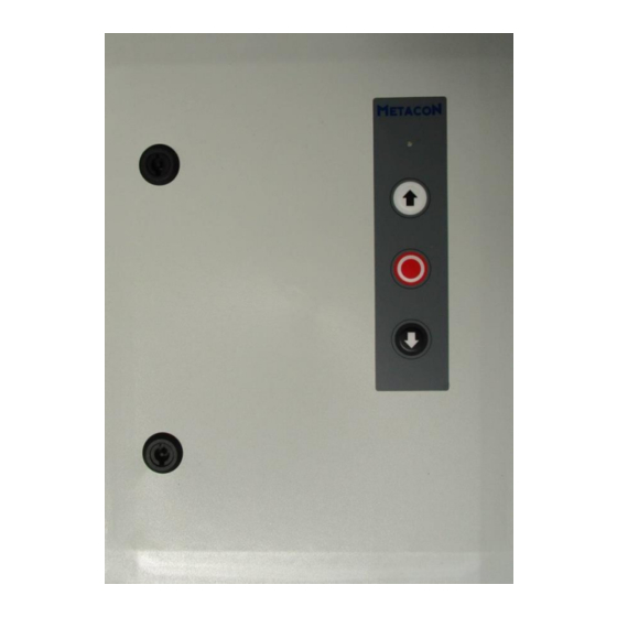
Door control FireProV2 Manual 11 Menu Settings can be set in the menu. On the PCB you will find 3 pushbuttons on the right side of the display: "˅", "˄" and "stop/OK" (see image). These work in normal operation as up-stop-down operation. - Page 33 Door control FireProV2 Manual Choice of safety edge .1 Disable safety edge and photo cell input (X12) and/or .2 Turn off photo cell. input photocell (X10) in Enable safety edge. Stop if safety edge is of fire case activated and after set time (parameter 0.5) continues to close.
- Page 34 Door control FireProV2 Manual 11.2 Parameter settings 1. : Parameter Description Settings End position open Open the door/roller shutter to the desired position and then press the stop/ok button on the print to confirm or press the lid button to cancel.
- Page 35 Door control FireProV2 Manual 11.3 Parameter settings 2. : Parameter Description Settings Motor duration 1 t/m 240 seconds monitoring sec. Function pulse input .1 Can’t stop in open direction when selecting parameter 0.1 on .2 Can stop in open direction automatic opening Automatically close 0 = Disabled...
- Page 36 Door control FireProV2 Manual 11.4 Parameter settings 3. : Parameter Description Settings Select limit switches in case of NES: fire .1 Use normal limit switch close to additional limit switch (S6 off) .2 Extra limit switch (S6) as "Overclose" limit switch .3 Use the normal limit switch close and use additional limit switch (S6) as an end...
- Page 37 Door control FireProV2 Manual 11.5 Parameter settings 4. : Parameter Description Settings Action at fire alarm NES: .1 Door/roller shutter immediately completely closed .2 Stop at additional limit switch (S6) Then close at time ( parameter 4.2) (not possible if parameter 3.1 is on 2) DES: .1 Door/roller shutter immediately completely closed...
- Page 38 Door control FireProV2 Manual 11.6 Parameter settings 5. : Parameter Description Settings Function "siren" output .1 Switches during pre-warning and when the door/roller shutter is moving .2 Switches only if the door/roller shutter is moving .3 Switches only in case of fire alarm, smoke detection or low battery voltage during pre- warning and if the door/roller shutter is moving...
- Page 39 Door control FireProV2 Manual Notifications If the 24 Volt DC power supply is present, the point on the left of the display will be lid. 24 VDC present When the control is switched off by means of the key switch on the cover, the point on the right side of the display will be lid.
-
Page 40: F; Error Messages
Door control FireProV2 Manual 12.2 F; Error messages: If the mains supply is present and there is no malfunction, the LED on the lid lights up green. When a malfunction occurs or the BMC or RMC input is active and the smoke detection is not reset, it lights red. - Page 41 Door control FireProV2 Manual F 2.4 8K2 safety edge activated The 8K2 safety edge is activated, this may be due to a obstacle in the door opening. If there is no on obstacle in the door opening and this notification continues to appear please check that the resistance on connector X11 (GND and 1K2/8K2 input) is still 8,2KOhm...
- Page 42 Door control FireProV2 Manual F 4.6 Light curtain activated Light curtain is activated. Photocell entrance interrupted. Make sure the beam of light is not interrupted. Whether the light curtain is properly connected and is not faulty. Check parameter 5.1, 5.2 or 5.3, if light curtain has been chosen. If no light curtain is connected, disable it at the appropriate parameter.
-
Page 43: Common Errors
Door control FireProV2 Manual 12.3 Common Errors Notification Description Recommendation/explanation F 3.1 Door past limit switch hold the open button on the circuit board for at closed least 5 seconds, after this 5 second the door/roller shutter will open when holding this button Hold to run open and can be set back between the final positions. -
Page 44: Declaration Of Conformity
Low voltage Directive 2014/35/EU RoHS Directive 2011/65/EU RDA BV, located at Spoorakkerweg 6 , 5071 NC Udenhout hereby declares that the product listed below complies with the above-mentioned EC directive and is intended solely for installation in a doorway as described in the manual. - Page 45 Door control FireProV2 Manual Please keep this manual with attachments carefully!
- Page 46 Manual Your installer: RDA B.V. | Spoorakkerweg 6 | 5071 NC Udenhout | General | T +31 (0) 416 66 00 44 | E info@rda-bv.nl | www.rda-bv.nl Service | T +31 (0) 416 23 50 39 | E service@rda-bv.nl | www.rda-bv.nl...
Need help?
Do you have a question about the FirePro V2 and is the answer not in the manual?
Questions and answers