
Related Manuals for Perfect Tuning Universal Gauge

Summary of Contents for Perfect Tuning Universal Gauge
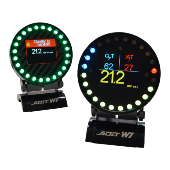
- Page 1 Universal Gauge Link ECU User Manual v1.4 For gauge hardware revision 4 and up, software version 48 www.PerfectTuning.net November 2017...
-
Page 2: Table Of Contents
Table of content Table of content ............................2 Warning ..............................4 Introduction .............................. 4 Wiring ..............................5 Connection to the Link G4+ or Vi-PEC ................... 5 1.1.1 Atom Header pinout: ......................6 1.1.2 Monsoon Header Pinout: ...................... 6 1.1.3 Kurofune Header Pinout ....................... 6 Menus and buttons .......................... - Page 3 Upgrade ..........................16 4.3.6 Admin ..........................17 Alarms ..............................17 Accessories and Sensors ........................19 Perfect Tuning Wideband controller: ..................19 6.1.1 Calibration procedure ......................19 EGT .............................. 19 Oil pressure sensor ........................20 Oil, coolant and air temperature sensor ..................20 Map sensors ..........................
-
Page 4: Warning
Race parts are inherently dangerous and may cause injury or damage if improperly modified or altered before use. Perfect Tuning will not be held liable for and will not pay you for any injuries or damage caused by misuse, modification, redesign, or alternation of any of our products. Perfect Tuning will not... -
Page 5: Wiring
1 Wiring Always disconnect the vehicle battery when installing the gauge. Do not leave any wires not isolated. Always solder or crimp the wires and protect with heat shrink. Refer to the user manual to connect the sensors. View when looking at the gauge. Color Function 12v ( + ). -
Page 6: Atom Header Pinout
1.1.1 Atom Header pinout: Viewed looking into ECU header (or wire side of loom connector) 1.1.2 Monsoon Header Pinout: Viewed looking into ECU header (or wire side of loom connector) 1.1.3 Kurofune Header Pinout Pins labeled J[1..8] are found on the JST connector on the rear of the ECU. www.PerfectTuning.net November 2017... -
Page 7: Menus And Buttons
2 Menus and buttons There are two buttons to navigate through the different menus of the gauge and edit basic settings. Press left to move to the left or to go up and press the right button to move to the right or go down. Press both buttons to select or enter. -
Page 8: Safe Mode
2.2.6 Safe Mode Safe mode is for firmware upgrade recovery in case of problems. Safe mode can also be accessed by pressing both buttons while powering the gauge. 2.2.7 Edit text color Change the text color in the menus and in few real-time display values. 2.2.8 Disable / Enable screen designer The screen designer is used to select which value is displayed in the real time screens. -
Page 9: Can Bus
3 CAN Bus The gauge can display values coming from the aftermarket ECU over the CAN bus 3.1 CAN bus resistor On the back of the gauge, there is a jumper for the 120 ohms end of bus resistor next to the cable connector. -
Page 10: Link G4+ And Vi-Pec I44 Or I88 Ecu Configuration
3.2.1 Link G4+ and Vi-PEC i44 or i88 ECU configuration Connect to you ECU using PCLink or iVTS software and go to ECU Controls, CAN Setup. Set the Mode to user defined, bit rate to 1 Mbit/s. Select channel 1 and select Transmit Generic Dash with transmit rate of 20 Hz. -
Page 11: Custom Values With Link G4 (Requires Gauge Firmware Version 60 And Up)
3.2.3 Custom values with Link G4 (requires gauge firmware version 60 and up). To display values that are not available on the “Generic Dash” stream, a custom stream is required. At this moment, only fuel content and temperature is available but if any other value is required, please contact us by email at support@perfecttuning.net and we’ll add it in the next firmware version of the... - Page 12 Then go to the “Streams” tab and add Frame 1 to Stream 1. Set “ID Position” to 0 and ID to 0. Add a parameter and select % Ethanol from the Fuel section. Start Pos: 8, Width: 8, MS First: Unsigned, Multiplier: 1, Divider: 1, Offset: 0.
-
Page 13: Wifi
4 WiFi 4.1 How to connect and access the gauge configuration webpage The gauge can be configured with any recent smartphone, tablet or laptop that is able to browse a webpage. Only one connection at the same time is supported. First, go to “Settings”... -
Page 14: Config
4.3.2 Config. The configuration page allows changing general settings of the gauge like units, LED ring intensity and more. The color tool is not available on IOS devices like iPhones and iPads. IOS users must enter the text color value in hexadecimal. Always hit “Save Settings”... -
Page 15: Alarms
4.3.4 Alarms This page is used to configure up to 16 alarms on the gauge. Each alarm can contain 2 conditions. Each field is explained by clicking on the question mark logo Alarms with a smaller number have higher priority. Always hit “Save Settings”... -
Page 16: Upgrade
4.3.5 Upgrade 1. Download the latest firmware upgrade file suited for your gauge (please verify your serial number) and select model required at http://perfecttuning.net under the support tab. 2. The firmware upgrade can be done with a smartphone, laptop or a tablet running Windows, Android or IOS. -
Page 17: Admin
4.3.6 Admin The admin page is used to do a factory reset of the gauge. The WiFi credentials section is for support and advanced users only. These settings are not related to the Wi-Fi hotspot SSID and password so do not try to change this. 5 Alarms The alarms are not configurable directly on the gauge. - Page 18 Require Ack is used to leave the alarm active as long as the user doesn’t acknowledge the alarm by pressing a button on the gauge. Eg: Channel is MAP (PSI). Condition is bigger, threshold is set to 20 and hysteresis is set to 1. Begin delay is set to 1 and end delay is set to 0.
-
Page 19: Accessories And Sensors
6.1.1 Calibration procedure When the wideband sensor is selected in the Inputs configuration menu, a reboot will be required for calibration. This will work only with the Perfect Tuning wideband controller. To cancel this calibration, press both buttons during the calibration sequence. -
Page 20: Oil Pressure Sensor
6.3 Oil pressure sensor The oil pressure sensor is compatible with oil, fuel, water or air pressure. Accuracy: within 1.5% of reading (full scale). Thread: 1/8”-27 NPT. Wiring connector: water sealed quick disconnect. Mating connector and wire harness (pigtail) are included. -
Page 21: Map Sensors
Configuration: Select “Oil temp” if the sensor looks like this even sensor is used as coolant temp sensor. Select GM CLT if the sensor looks like this: Select GM IAT if the sensor looks like this: 6.5 Map sensors 6.5.1 GM 3 bar map sensor The GM 3 bar (29 psi) and 4 bar (44 psi) must be connected this way. -
Page 22: Buzzer
Oxygen sensors are considered wear items and are not covered under warranty. Please note that before Perfect Tuning can issue an RMA for any electronic product, it is first necessary for the installer or end user to contact us at support@perfecttuning.net to discuss the problem. Under no circumstances should a system be returned or a RMA requested before the above process transpires. -
Page 23: Dimensions
Perfect Tuning electronic parts. Parts used in the repair of Perfect Tuning electronic components will be extra. Perfect Tuning will provide an estimate of repairs and receive written or electronic authorization before repairs are made to the product...
Need help?
Do you have a question about the Universal Gauge and is the answer not in the manual?
Questions and answers