Table of Contents
Advertisement
Quick Links
Advertisement
Table of Contents

Related Manuals for Dentech AyrDyne


Summary of Contents for Dentech AyrDyne
- Page 1 Installation, Operation, and Maintenance Manual www.ayrdyne.com...
- Page 2 www.ayrdyne.com...
-
Page 3: Table Of Contents
........42 www.ayrdyne.com... -
Page 4: Introduction
INTRODUCTION The purpose of this document is to outline proper installation, maintenance, operation, and care of the AyrDyne® Monitoring System Human Machine Interface (HMI). This document is in no way intended to be used to determine the reliability of this product outside of its originally intended application. -
Page 5: Overview
Failure to follow safety protocol for this and any other system could result in serious bodily harm or other injury. No responsibility is assumed by DenTech for any consequences arising out of the use of this material. www.ayrdyne.com... -
Page 6: Installation And Removal
RESULT IN INJURY, OR EQUIPMENT DAMAGE. WARNING! ELECTRICAL SHOCK HAZARD EXISTS - Ensure that the control enclosure within which you are working is powered down and locked out. - Verify that all power sources are in a zero energy state. FAILURE TO FOLLOW THESE INSTRUCTIONS MAY RESULT IN INJURY, DEATH, OR EQUIPMENT DAMAGE. Figure 2.3.1a Front view of HMI. Figure 2.3.1b Rear view of HMI. www.ayrdyne.com... -
Page 7: Removal Of Hmi
2.1 REMOVAL OF HMI Pull green connector downward to remove power connection from HMI. Use a T-20 Torx screwdriver to remove the ground wire. Figure 2.3.1c Power connection removed from HMI. Figure 2.3.2 Ground wire with T-20 Torx screw. www.ayrdyne.com... - Page 8 HMI to the control enclosure door using a small flat head screwdriver. Make sure to support the HMI with the other hand. Continue to loosen fasteners until they can be removed from the HMI. Figure 2.3.3 Loosening HMI fasteners. Figure 2.3.4 Installation fasteners removed. www.ayrdyne.com...
-
Page 9: Installation Of Hmi
INSTALLATION & REMOVAL REMOVAL & INSTALLATION Once the installation fasteners have been removed, gently remove the AyrDyne HMI from the front of the enclosure door, taking care not to damage or displace the installation gasket. 2.2 INSTALLATION OF HMI To install the HMI, follow the steps on pages six through nine in reverse order. -
Page 10: Removal Of Plc
INSTALLATION & REMOVAL INSTALLING & REMOVING PLC For the removal of the PLC portion of the AyrDyne Siemens S7-1200 Manual System Manual, 04/2012, Monitoring System, please visit the AyrDyne website A5E02486680-06 for a link to the Siemens installation manual. Pages 50-55 2.3.1 INSTALLING &... -
Page 11: An Sb, Cb, Or Bb
4. Gently pry the module up to disengage it from the CPU. 5. Remove the module straight up from its mounting position in the top of the CPU. 6. Replace the cover onto the CPU. 7. Replace the terminal block covers. www.ayrdyne.com... -
Page 12: Installing Or Replacing
1. Place a screwdriver beside the tab on the top of the SM. 2. Slide the tab fully to the left to extend the bus connector into the CPU. Follow the same procedure to install a signal module to a signal module. www.ayrdyne.com... - Page 13 2. Rotate the SM up and off the rail. Remove the SM from the system. 3. If required, cover the bus connector on the CPU to avoid contamination. Follow the same procedure to remove a signal module from a signal module. www.ayrdyne.com...
-
Page 14: Cm Or Cp
4. Remove the CPU and CMs from the DIN rail or panel. 5. Grasp the CPU and CMs firmly and pull apart. CAUTION! Do not use a tool to separate the modules because this will damage the units. www.ayrdyne.com... -
Page 15: Block Connector
3. Align the wiring edge of the connector inside the rim of the connector base. 4. Press firmly down and rotate the connector until it snaps into place. Check carefully to ensure that the connector is properly aligned and fully engaged. www.ayrdyne.com... -
Page 16: Operation
OPERATION SCREEN OVERVIEW This section covers the navigation and operation of the standard AyrDyne monitoring system. The operation and functionality of each screen is covered in detail in later sections. The table below shows the layout of the screens. Available screens depend on system requirements and configuration. -
Page 17: Status Bar
The navigation bar is located at the bottom of each screen and can be used to navigate through the various systems. The underline indicates the section currently displayed. The circle with the exclamation symbol denotes when a section is in alarm. AYRDYNE DISCHARGE This button displays the home screen... -
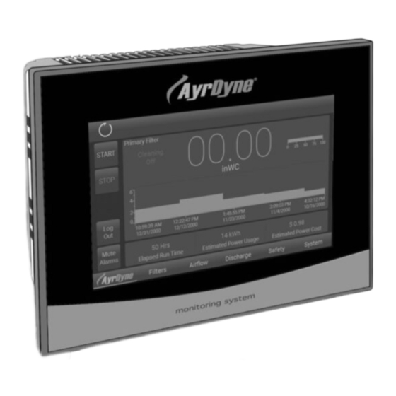
Page 18: Home
OPERATION SCREEN OVERVIEW 3.1.3 HOME The home screen serves as the overview for the system. This screen will be the first screen displayed once the system is powered up. www.ayrdyne.com... - Page 19 This numeric display shows the run time of the system. ESTIMATED POWER USAGE (MWh) This numeric display shows estimated power usage if equipped with a VFD. ESTIMATED POWER COST (USD) This numeric display shows estimated power usage cost if equipped with a VFD. www.ayrdyne.com...
-
Page 20: Filters
Saves the settings for later use. CLEAN MODE SELECTION Load This multi-selector sets the type of filter Loads previously saved settings. cleaning performed by the system. There Hold To Reset are three types of cleaning: On Demand, On Resets settings to factory defaults. www.ayrdyne.com... - Page 21 CLEAN STOP SET POINT This numeric entry/display shows the set point that the differential pressure must fall below to stop On Demand cleaning. This value is adjustable between minimum transmitter output and the Clean Start Set Point. Recommended setting is 1.2 inWC. www.ayrdyne.com...
-
Page 22: Hand Clean
In addition, the monitoring device will also detect air leaks on the solenoid manifold, at which time it will alarm. The leak can also be pointed to a solenoid if it started after a specific solenoid was pulsed. www.ayrdyne.com... -
Page 23: Secondary Filter
This value is adjustable SECONDARY FILTER DP between the minimum and maximum This numeric display and bar graph show the transmitter outputs. Recommended setting filter differential pressure measured between is 6 inWC. the dirty and clean sides of the filters. www.ayrdyne.com... -
Page 24: Airflow
Save Saves the settings for later use. Increasing Blower Speed System is running below the minimum Load set point and increases blower speed in Loads previously saved settings. order to increase airflow. Hold To Reset Resets settings to factory defaults. www.ayrdyne.com... - Page 25 Change this value to adjust how the blower responds to changing readings of static, velocity, or flow. This value is adjustable between 0 and 5000 milliseconds (ms). Factory default setting is 500ms. www.ayrdyne.com...
-
Page 26: Vfd Settings
ACCELERATION TIME (s) MOTOR VOLTS (VAC) This numeric entry/display shows the This numeric entry/display shows the motor acceleration time. This value is adjustable voltage. Set to the motor nameplate rated volts. between 1 and 500s. Factory default setting is 30s. www.ayrdyne.com... - Page 27 OUTPUT FREQUENCY (Hertz) This numeric display shows VFD output frequency. OUTPUT CURRENT (A) This numeric display shows VFD output current. DC BUS VOLTS (VDC) This numeric display shows the VFD DC Bus voltage. www.ayrdyne.com...
-
Page 28: Discharge
3.4.1 ROTARY VALVES CAUTION! USE CAUTION WHEN MANUALLY ENABLING ROTARY VALVE AIR LOCK Be sure all personnel are clear and equipment is in mechanically sound condition. Failure to follow this instruction could result in equipment damage, injury, or death. www.ayrdyne.com... - Page 29 Follow LOTO rules when servicing. AUTO This button places the rotary valve into Auto Mode. When engaged, the valve will run if the blower is running, or if the system is cleaning the primary filters. www.ayrdyne.com...
-
Page 30: Double Dump
This button places the rotary valve into Auto Load Mode. When engaged, the valve will run if the Loads previously saved settings blower is running, or if the system is cleaning the primary filters. Hold To Reset Resets settings to factory defaults www.ayrdyne.com... - Page 31 This numeric entry/display shows how long the valves have to open or close before a position fault is produced. This value is adjustable between 0 and 10s. Factory default setting is 10s. If set to 0, position fault is disabled. www.ayrdyne.com...
-
Page 32: Safety
Safety relay circuit status: All devices in safety circuit are set OPEN At least one device in the safety circuit EVENT DETECTED: is not set OUTPUT K1/K2 Safety relay condition: Safety Relay is set TRIPPED Safety Relay is tripped www.ayrdyne.com... -
Page 33: System
Powering off the system will clear this table. MUTE ALARMS This button is only visible when the system is equipped with an alarm horn. This button will mute any active alarms. New alarms will reactivate the horn. www.ayrdyne.com... -
Page 34: Settings
(DST). FACTORY RESET SET DATE This button resets all settings and data to This text entry/display allows the user to factory defaults. Note that this will delete all change the date of the system. data. www.ayrdyne.com... -
Page 35: I/O
ANALOG INPUTS / OUTPUTS button is gray, the input remains as wired; This graphic display shows the signal of each when the “inv” button is blue, the input state analog input / output from 0 – 100%. is inverted. www.ayrdyne.com... -
Page 36: Metrics
OPERATION SYSTEM 3.6.4 METRICS www.ayrdyne.com... - Page 37 This numeric entry/display shows power rate, if equipped with a VFD. HOLD TO RESET This button will reset the blower metrics. This button must be held until all indicators in the button turn blue, which takes approximately 3 seconds. www.ayrdyne.com...
-
Page 38: Service Reminders
OPERATION SYSTEM 3.6.5 SERVICE REMINDERS www.ayrdyne.com... - Page 39 This selector changes the system maintenance calculation method. Calculation is based on the DP reading Run Time of the filter. The AyrDyne will detect Calculation is based on system run non-recovery of the filter DP in the time which is incremented anytime current cleaning range.
-
Page 40: Troubleshooting
Clear any material from valve • Sensor needs adjustment • Verify proper chain tension Double Dump Valve Bypassed • Double Dump Valve OFF while the • Place the Double Dump Valve in either AUTO or HAND system is running mode www.ayrdyne.com... - Page 41 Failure to follow safety protocol for this and any other system could result in serious bodily harm or other injury. No responsibility is assumed by DenTech for any consequences arising out of the use of this material. www.ayrdyne.com...
-
Page 42: Glossary
SP is measured between the dirty side of the filter and atmosphere. The higher the number, the more suction capacity. VARIABLE FREQUENCY DRIVE (VFD): A motor control system that manipulates output frequency in order to run an electrical motor at any desired speed. www.ayrdyne.com... - Page 43 NOTES www.ayrdyne.com...
- Page 44 Installation, Operation, and Maintenance Manual 1975 N. Reading Road, Denver, PA 17517 717-335-4820 | www.ayrdyne.com AD-IOM R0 2/18 ©2018 DenTech, Inc.
Need help?
Do you have a question about the AyrDyne and is the answer not in the manual?
Questions and answers