Table of Contents
Advertisement
Quick Links
Advertisement
Table of Contents

Related Manuals for Huaqi Zhengbang ZB3245TSS

Summary of Contents for Huaqi Zhengbang ZB3245TSS
- Page 2 Introduction Thank you for using this product. This operation manual provides the parameters, operation guidance and other related information of ZB3245TS chip mounter. !Attention: 1. It is strictly prohibited to copy part of or the entire book (including software and programs) without authorization. 2.
-
Page 3: Table Of Contents
Directory Introduction Safety precautions Chapter 1 Prepare work before use..........................1 Chapter 2 Equipment Summary.............................2 2-1 Equipment Constitute..............................2 2-2 X, Y, Z and R axis Description..........................3 2-3 File Type..................................3 2-4 Equipment Parameters..............................4 2-5 Nozzle.....................................5 2-6 Substrate Limiting Condition...........................5 2-7 Menu Constitute................................ -
Page 4: Chapter 1 Prepare Work Before Use
Trouble Shooting ZB3245TSS-Rev1.0 Chapter 1 Prepare work before use 1.Open the wooden box, take out the machine and accessories, check the equipment list and check whether all parts are in good condition. If you have any further question, please contact us. -
Page 5: Chapter 2 Equipment Summary
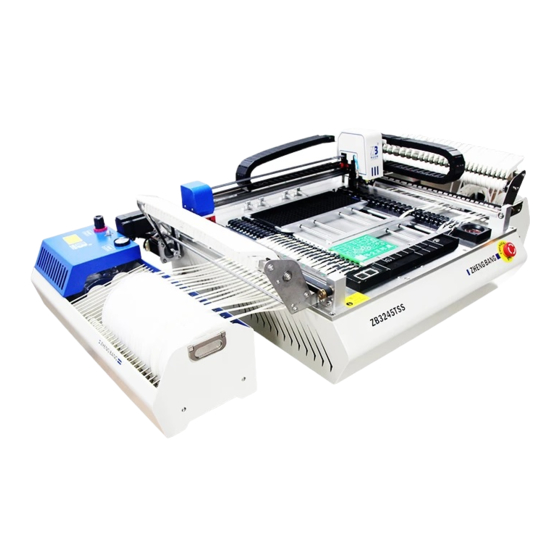
Trouble Shooting ZB3245TSS-Rev1.0 Chapter 2 Equipment Summary 2-1 Equipment Constitute Fig.2-1 Host structure 1.Y-axis stepping servo motor 2. Operation platform 3.X-axis linear slide rail 4.Pin 5.Mounting head 6.Y-axis guide rail 7.X-axis stepping servo motor 8 .Button for emergency stop 9.HD Camera 10. -
Page 6: X, Y, Z And R Axis Description
Trouble Shooting ZB3245TSS-Rev1.0 Fig.2-6 Mounting head structure Fig.2-7 Operation platform structure 33.Vacuum checkerboard 34.Z-axis extension spring 35.Electric rotating machinery 36. Pull needle test part 37.Pin 38.2# nozzle 39.1# nozzle 40.Material groove 41.RC Camera 42.IC tray holder 43.PCB board adjustable support 44.PCB board movable mount 45.PCB board fixed mount... -
Page 7: Equipment Parameters
Trouble Shooting ZB3245TSS-Rev1.0 2-4 Equipment Parameters System Items Content Mounting head number 2 pieces Mounting accuracy 0.05mm Mounting angle 0~360° Theoretical Velocity 7000pcs/hour Mounting Normal mounting 5000pcs/hour System Visual Mounting 3500pcs/hour Nozzle type Juki nozzle RC (0402, 0603, 0805, 1206, etc) -
Page 8: Nozzle
Trouble Shooting ZB3245TSS-Rev1.0 2-5 Nozzle External Inner diameter Appearance Applicable component diameter Φ0.7mm Φ0.4mm 0402 Φ1.0mm Φ0.6mm 0603 Φ1.5mm Φ1.0mm 0805、1206、1210、SOT23 Φ3.5mm Φ1.7mm SOP8、SOP14、1812、2220 Φ5.0mm Φ3.2mm QFN、TQFP、BGA 2-6 Substrate Limiting Condition Fig.2-8 Substrate Limitation... -
Page 9: Menu Constitute
Trouble Shooting ZB3245TSS-Rev1.0 2-7 Menu Constitute Fig.2-9 Main Menu Fig.2-10 Edit Menu Fig.2-11 Menu Setup Fig.2-12 Coordinate Edit... -
Page 10: Chapter3 System Settings
Trouble Shooting ZB3245TSS-Rev1.0 Chapter3 System Settings 3-1 Vacuum setting Fig.3-1Vacuum setting 1.Open vacuum detection switch Tick “working detection” with “√”to start vacuum detection,System judges “sucking up” successful or not automatically, Decide next action according to result.Erase “√” to close vacuum detection switch. -
Page 11: Nozzle Adjustment
Trouble Shooting ZB3245TSS-Rev1.0 3-3 Nozzle adjustment The adjustment function mainly works on coordinate offset of top camera, bottom camera and nozzle and keep nozzles in same center to ensure pasting precision. Adjustment is finished during exiting factory test and no need to adjust in common replacing. Offset resulted from abrasion of machine and nozzle problem can all be corrected by nozzle adjustment. -
Page 12: Pin Calibrate
Trouble Shooting ZB3245TSS-Rev1.0 3-4 Pin calibrate Click "set --nozzle -- calibration" to move the coordinates to the position of the center of the pull needle, confirm and save. Fig.3-5 Pull needle calibration Chapter4 Quick operating instructions Operation process: Step 1:... -
Page 13: Step 2:Edit The Program
Trouble Shooting ZB3245TSS-Rev1.0 NO.1-2 How to Load feeders Put the prepared feeder plate on the feeder location, pass the material belt through the polished rod and gets stuck in the material tank, and then peel off about 200mm of feeder tape and press it under the press wheel. - Page 14 Trouble Shooting ZB3245TSS-Rev1.0 NO.2-2 PCB Original Point Edit Open the pick and place machine software, click “Edit-PCB”, double click “X/Y” Coordinate bar to find the coordinate edit frame. Fig.4-5 PCB Original Point !Attention: The original point coordinate must be the same as the step NO.2-1 in CSV file.
- Page 15 Trouble Shooting ZB3245TSS-Rev1.0 NO.2-5 Feeder Edit Click “edit-feeder” to log in the feeder edit mode. component value and type Input the feeder no., open the switch;Input the !Attention: The component value and type must be the same as the CSV file(included the capital and small letter ) 1.Edit the feeder angel, height, components thickness, Z axis speed,choose the nozzle.
-
Page 16: Step 3:Production
Trouble Shooting ZB3245TSS-Rev1.0 Step 3:Production Click “Product-Open” to input the PCB file, then click “Matching” to find the feeders, then click “Start” to start the production. Fig.4-12 Production Chapter 5 Maintaining 5-1 Routine Maintenance 1.Check whether the nozzle tip is worn or damaged, and whether the nozzle is blocked or pasted by solder paste, replace or clean it when necessary. -
Page 17: Nozzle Cleaning
Trouble Shooting ZB3245TSS-Rev1.0 10.Check if there’s any looseness on outer silicone ring of nozzle base and replace if necessary. !Danger: In order to prevent accident caused by accidental start, please cut off the power supply for maintenance. !Warning: Do not use the blower gun to blow dust and debris because dust and debris may be blew inside the machine and adhered to the guide rail, lead screw, lens and affect normal operation of the machine.
Need help?
Do you have a question about the ZB3245TSS and is the answer not in the manual?
Questions and answers