Table of Contents
Advertisement
Quick Links
Advertisement
Table of Contents

Summary of Contents for Audio Gear Obsession SUMMINGFACILITY
- Page 1 SUMMINGFACILITY User’s Manual Audio Gear Obsession...
-
Page 2: Table Of Contents
10 Declaration of Conformity List of Figures SUMMINGFACILITY Scheme ....Input Jacks ..... -
Page 3: Warranty
1 Warranty Audio Gear Obsession warrants this product to be free of defect and malfunctions for a period of two years from the date of purchase (invoice date). Malfunction caused by improper use of this device such as: • Wrong power supply connection •... -
Page 4: Block Scheme
Stage Stage Stage Stage Direct Meter R Level Meter L Gain Gain Level Level Send A Send B Level Master Master Σ Σ Σ Σ Mute Mute Mute Master Bus Aux Bus A & B Figure 1: SUMMINGFACILITY Block Scheme... -
Page 5: Panel Control
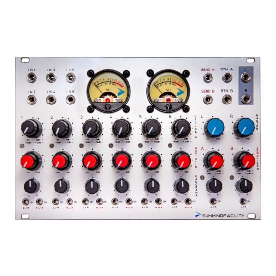
The Input Jacks for the 6 Audio Channel are located the top left side of the panel. Figure 2: Input Jacks SUMMINGFACILITY features six 3.5 mm Balanced Inputs Jacks, bal‐ anced inputs accomodates interconnection between outside/inside Eurorack Domain (Unbalanced). Standard 3.5 mm Mono Patch cable... -
Page 6: Channel Strip
The range of gain control is from ´10 dB to +12 dB relative to input level. The blue dot on the panel correspond approximately to unity gain. SUMMINGFACILITY’s knobs are not center detent. • 1 Channel LED: The led monitors signal activity after gain stage. -
Page 7: Master Section
• 5 Aux Switch: ON position: connect the Channel to aux stereo bus. OFF position: Mute DESIGN NOTE (PAY ATTENTION): as seen on the channel settings description above, SUMMINGFACILITY uses the following convention for the stacked dual knobs: UPPER KNOB(inner shaft) –> UPPER CONTROL ON THE PANEL;... - Page 8 • 6 Send A & Return A: The upper knob sets the level of the Aux Send A (”SEND A” on the panel) to the Send A Output Jacks (see sections below). The lower knob sets the gain for the Return A (”RTN.”...
-
Page 9: Stereo Master
4.2.2 Stereo Master Figure 5: Stereo Master • 14 Left Master Output: Controls the Stereo left master output level after the summing stage. Range is from ´8 dB to 0 dB range. • 15 Right Master Output: Controls the Stereo right master output level after the summing stage. -
Page 10: Vu Meter
5 Vu Meter Figure 7: Vu Meter SUMMINGFACILITY features 2 Analog Vu‐Meters. The mixer ships pre‐ calibrated. Vu‐Meters monitor signal’s activity after master bus output. However, depending on the environment and setup, calibration over time might be required. Vu Meter Calibration steps will be enumerated in the following section. -
Page 11: Vu Meter Calibration
6 Vu Meter Calibration Figure 9: Vu Meter Trimmers To starts the vu‐meters calibration, first grant access to the pcb side of the module. Take a look at Figure 9. 16 and 17 are, respectively, the Right Vu‐Meter (R_Trim on the PCB) and Left Vu‐Meter (L_Trim on the PCB). -
Page 12: Power Connection
See Figure 10. Figure 10: Power Connector 8 Direct Output SUMMINGFACILITY features Direct Out on each of the six channels. Refer to Figure 1 to further information about the Direct Out position on the signal’s path. This feature will be avaible in... -
Page 13: Specifications
9 Specifications In the following table, mechanical and electrical specifications will be provided. Parameter Value Width 38HP (193 mm) Height +12 V consumption 170 mA (225 mA with Meters On) ‐12 V consumption 170 mA (225 mA with Meters On) Recommended Positive Voltage 12 V Recommended Negative Voltage...


Need help?
Do you have a question about the SUMMINGFACILITY and is the answer not in the manual?
Questions and answers